  |
 Alan
Stummer Alan
Stummer Research Lab Technologist | |
 |
DigiPID - Digital PID Machine
Warning: This is a work in progress. Take
everything with a
grain of salt! |
Downloads
| I am curious who uses what. Are these web pages a waste of time, or are they any help to others? Are the circuits, software and utilities appearing in other labs? Please send your comments or suggestions or what you have used (or not) or schematics of your version or pictures or anything! Email me, or be creative and send a postcard! I want to hear from the vacuum! |
Links |
| NOTICE: This web page and associated files are provided for reference only. This is not a kit site! It is a collection of my work here at the University of Toronto in the Physics department. If you are considering using any schematics, designs, or anything else from here then be warned that you had better know something of what you are about to do. No design is guaranteed in any way, including workable schematic, board layout, HDL code, embedded software, user software, component selection, documentation, web pages, or anything. All that said, if it says here it works then for me it worked. To make the project work may have involved undocumented additions, changes, deletions, tweaks, tunings, alterations, modifications, adjustments, waving of a wand while wearing a pointy black hat, appeals to electron deities and just plain doing whatever it takes to make the project work. | ||
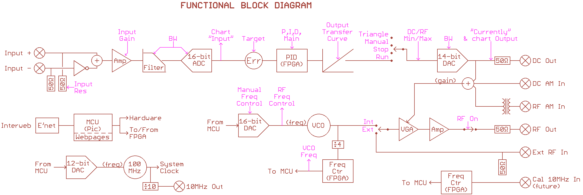
Started in 2016 Sept for Joseph's lab. The name, DigiPid, is an abbreviation of Digital PID (Proportional, Integral, Derivative gains). It is a generic realtime digital controller with a FPGA (for realtime operations), ADCs and DACs, TTL inputs and USB and/or Ethernet interface. The output is either RF (as determined by the plug-in VCO) for use with AOMs or direct DC up to ±10V. At power up, the MCU loads the latest operating parameters into the FPGA. This allows it to be a stand-alone unit. When connected to a host via USB or Ethernet, it can store new operating parameters. The host, when connected, can monitor operations and change parameters.
The MCU is a MicroChip PIC32MZ, the FPGA is an Altera MAX10. There is be a stable 24MHz clock onboard. The ADC is 16-bit (15-bit plus sign) and the DAC is 14-bit, both at up to 2.5MSPS. ADC input is differential bipolar. Several TTL inputs allow for functions such as outputs enabling, freezing outputs, etc, while a couple of TTL outputs allow for future dedicated flags.
The HDL (Verilog) runs a standard PID with parameters set by
the MCU
and features such as several definable non-linear sections in its
transfer curve. This latter is difficult or impossible with analog
circuits.
Coming soon! Stay tuned!
| Parameter | Min | Typ | Max | Description and Conditions |
| Input voltage | ??? | |||
| DC output range | -10V | +10V | User settable limits | |
| DC output resolution | 1.22mV | 14-bits over 20V | ||
| DC output resistance | 50Ω | |||
Return to homepage
| Please direct questions, queries, broken links, problems, flak, slings, arrows, kudos, criticism, comments, remarks, gossip, redactions, brickbats, corrections and suggestions to astummer_at_physics.utoronto.ca. | 
|

