PHY405 Electronics, Lab 5
Adapted from Prof. David Bailey's website in 2022
Overview
A mini-project to build a system to automatically measure temperature. Topics include:
- Thermistor
- Voltage regulator
- Arduino micro-controllers
- Analog-to-Digital Converter (ADC)
- Op-amp Follower
- Communicating with the Arduino via Python.
Background preparation before starting the lab
Before the lab, do anything (e.g. design, analyze, read, watch, …) that can be done before the lab.
- Several exercises should be answered, wholly or in part, before the lab.
- Look at the Arduino IDE. If downloaded onto your own computer, this allows you to
- Write and compile code so it is ready to try when you come into the lab.
- You will likely run out of time if you start from scratch coding in the lab.
- Write and compile code so it is ready to try when you come into the lab.
- If you are not familiar with the Arduino, before the lab you may want to play with TinkerCad simulations of Blink or other Arduino examples.
- Requires you to create a free account.
Safety Reminders (for both humans and electronics)
Unless a high current is needed, it is best to set the current limit on your supply to <50ma, to reduce that chance that components will be damaged if circuits are miswired.
- If your circuit starts to smoke, turn off the power to the circuit!
- So far this semester, at least 3 components have been smoked.
The Arduino is easy to fry due to static. BE CAREFUL!!
- Static discharges can destroy equipment and component. It is easy to generate kilovolt discharges if you wear synthetic clothing, sit on a plastic chair, or walk/roll in a chair across a carpet.
- Always discharge yourself before touching any components.
Arduino analog input pins are electronically fragile and can sometimes fail in ways that are not immediately obvious.
- Voltages less than 0V or greater than 5V must never be applied to the Arduino analog input pins!
Exercises
Measuring a thermistor’s output
A thermistor is a resistor whose resistance (\(R_t\)) depends on temperature as shown in Figure 1. You will be using a Vishay NTCLE100E3103HB0 thermistor](http://www.farnell.com/datasheets/2792960.pdf), an NTC type with a negative temperature coefficient, i.e., its resistance decreases with temperature. Its nominal resistance at \(25^\circ\mathrm{C}\) is \(R_{25} = 10 \mathrm{k}\Omega\).
The thermistor’s datasheet provides the following formula for converting its resistance to temperature in Kelvin:
\[\frac{1}{T(R_t)} = A_1 + B_1\ln\frac{R_t}{R_{25}} + C_1\left(\ln\frac{R_t}{R_{25}}\right)^2 + D_1\left(\ln\frac{R_t}{R_{25}}\right)^3 \]
The constants for this thermistor type (in units of \(K^{-1}\)) are \(A_1 = 3.354016 \times 10^{-3}\), \(B_1 = 2.884193 \times 10^{-4}\), \(C_1 = 4.118032 \times 10^{-6}\), \(D_1 = 1.786790 \times 10^{-7}\).
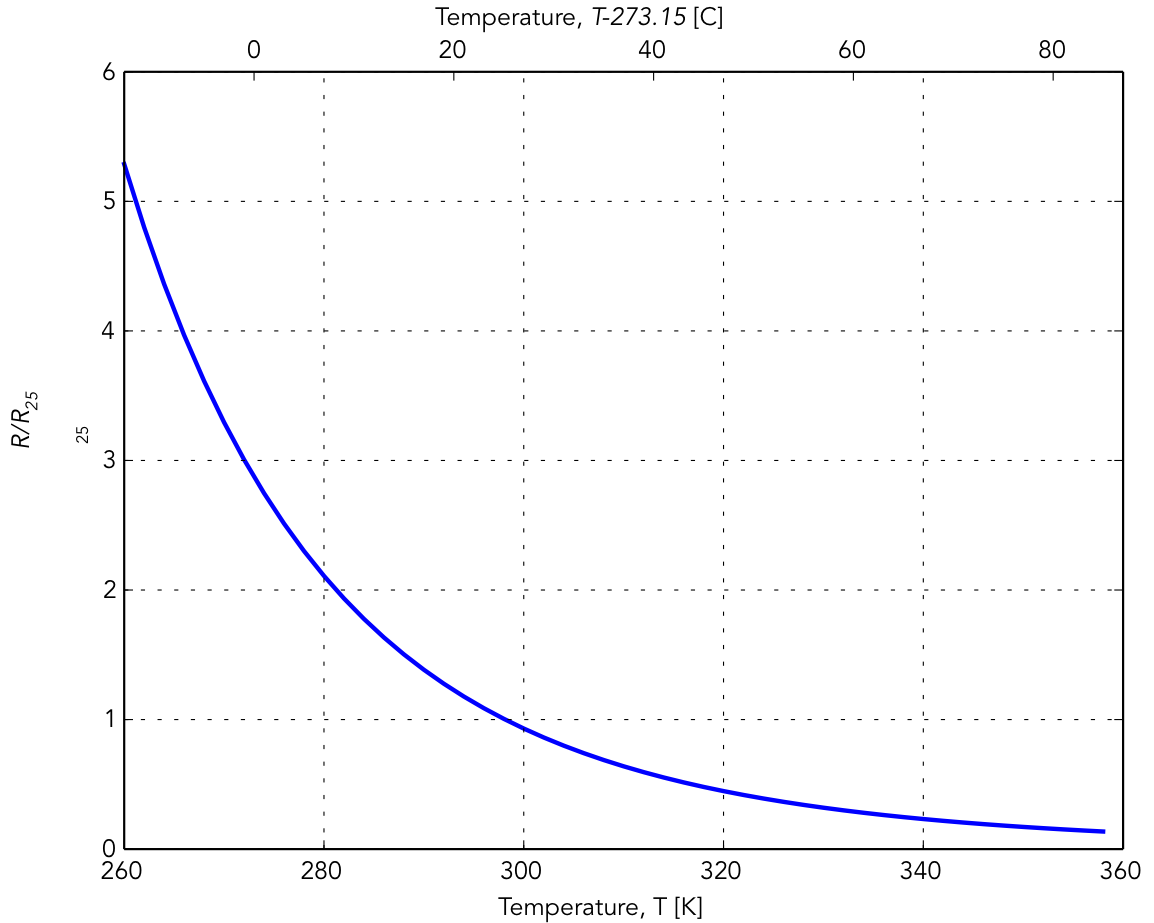
Resistance versus temperature for a negative temperature coefficient (NTC) thermistor. \(R_{25}\) is the nominal resistance of the thermistor at 25 C.
R-1) Measure the resistance of the thermistor, \(R_{th}\), at room temperature using your multimeter. Record the room temperature (available from the Instructor) and verify that the observed value of \(R_{th}\) is reasonably consistent with the expected value.
In order to automatically record the thermistor’s resistance, it is convenient to produce a voltage that depends on its resistance. Do this using a voltage divider as shown in Figure 2. Use a measured 10k resistor for \(R_{ref}\), and \(V_{in} = +5\mathrm{VDC}\).
- The optimal value for the reference resistor is one that makes the reference voltage (\(V_{ref}\)) most sensitive to changes in the thermister resistance around \(25^\circ\mathrm{C}\), i.e. you want to maximize \(\frac{dV_{ref}}{dR_t}\) around \(25^\circ\mathrm{C}\). This turns out to be when \(R_{ref}\sim R_{25}\).
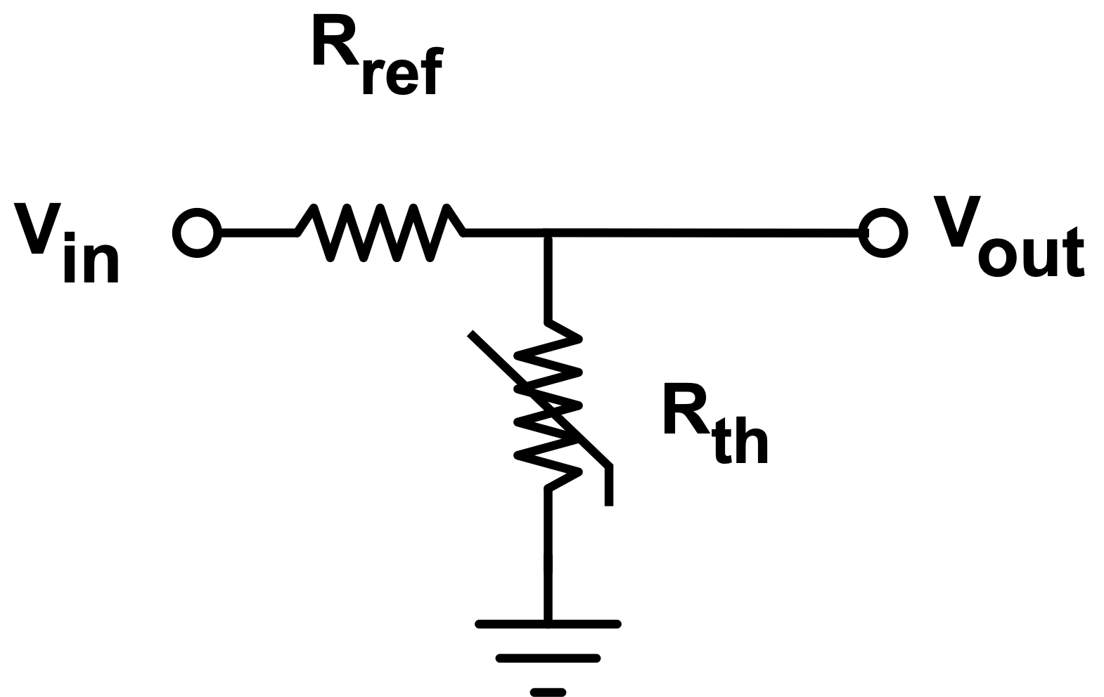
Divider circuit to convert the thermistor’s resistance (\(R_{th}\)) to a measureable voltage.
R-2) Use the divider to measure the thermistor’s resistance when you hold the thermistor’s head between thumb and forefinger for a while. Estimate your hand’s temperature using the thermister conversion formula.
- Since we want to qualitatively see the effect of warming the thermistor above room temperature, this works best if the room is cool and your fingers are warm.
Arduino Microcontroller
The voltage produced by the thermistor divider circuit is a complicated function of the temperature, so it would be convenient to directly convert the thermistor’s output into a temperature. A digital device called a microcontroller can automate this measurement and calculation. Microcontrollers are extremely versatile devices, and are handy for many tasks where complicated algorithms and nonlinear operations need to be implemented.
Arduino Setup
WARNING: To avoid zapping - and possibly destroying - your Arduino with a static discharge, it is best to ground yourself before touching your Arduino.
Plug in your Arduino board into any available USB port your computer.
The Arduino IDE should already be available on the desktop of the lap computer, but if not - or if you wish to use your own laptop - download and install it.
- Your laptop will need USB-A ports or an adaptor.
Start up the Arduino program on the desktop, and configure the software to communicate with an Arduino Uno board.
- Make sure that the
Boardunder theToolsmenu is chosen to be Arduino Uno, and thePortis chosen to be the one with Arduino Uno in its name.
To upload and run a program (called a “sketch”) to the Arduino, you first need to compile it, and upload it (using the button shaped like a right arrow). Try the simple Blink example first:
- Select
File\(\rightarrow\)Examples\(\rightarrow\)01.Basics\(\rightarrow\)Blink - Compile
Blinkby clicking onSketch\(\rightarrow\)Verify/Compileor on theVerify“check mark” button. - Upload
Blinkto the Arduino by clicking onSketch\(\rightarrow\)Uploador on the “right arrow”Uploadbutton. - The “L” LED on your Arduino should start blinking every second.
- There are 3 LEDs on the Arduino board, labelled “L”, “Tx”, and “Rx”. the latter two show the Arduino is transmitting or receiving.
Arduino sketches are written in a version of C++ that is described in the Arduino Language Reference. There are many, many examples, tutorials, videos, and other Arduino help and documentation available online.
Play with the code to become familiar with the programming interface, changing the code so the LED blinks in a different pattern. After modifying the code, it is usually sufficient to click Upload to compile and upload it.
- Note that the delays in the code are in milliseconds
R-3) Include your Arduino code in your report and describe what pattern it makes.
R-4) Make a short (<10 second) video showing your Arduino blinking in the pattern defined by your code, and submit via Quercus along with your report.
- The size of your video file should be <10MB; 720p is more than enough resolution.
Voltage source
A device’s power supply typically provides only one voltage, but it is often the case that that different components within the device require different voltages. For example, the op-amp used later in this exercise may use \(\pm15\)V, but we only want a maximum of 5 V input into the Arduino. Another common issue is that the input voltage is not known exactly a priori, but we need to supply a precise voltage to a circuit.
In this task you will use an LM7805 voltage regulator IC to generate a precise and stable voltage.
Wire up a 7805 regulator on your breadboard as follows:
- Connect your positive (Channel 2) DC power supply to the input pin of the 7805 (pin 1) The pin labels are listed in the IC’s datasheet.
- Connect the power supply Channel 2 COMMON output to the ground pin of the 7805 (pin 2).
- As with op-amps, we want to short any high frequency noise to ground, so connect both pins 1 & 3 to ground with capacitors.
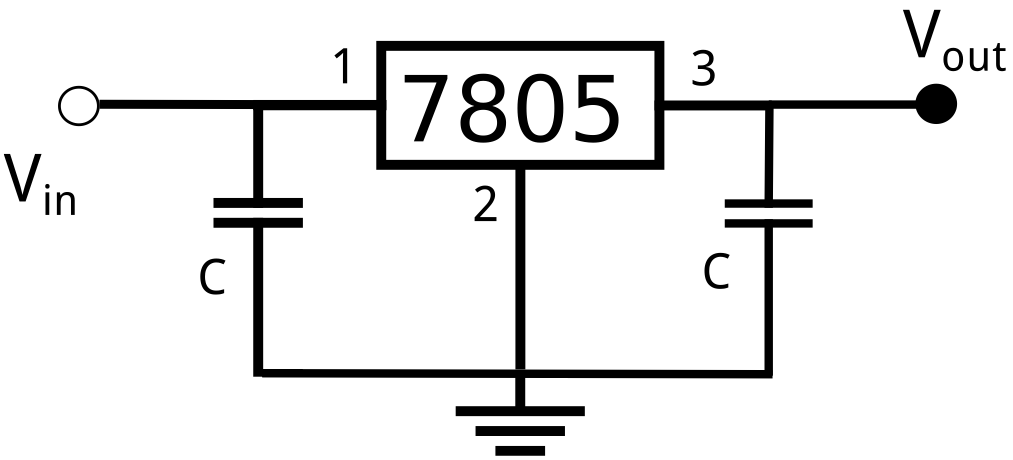
Circuit for testing the LM7805 voltage regulator. Choose capacitors between 0.1 and 1 µF.
R-5) Connect the output (pin 3) of the 7805 to ground with a 1k resistor. Use your multimeter to measure (and report) the output voltage for input voltages of 5, 7, and 25V. What is the percentage difference in the the output voltage between 7 and 25V input voltages?
Except for removing the 1K resistor, do not disassemble this circuit. You will use it later.
Arduino Analog Input
The analog inputs of the Arduino are connected to a 10-bit analog-to-digital converter with a voltage range from 0 to 5 V.
WARNING: Applying voltages outside the range of 0 to +5 V to the Arduino analog input pins may destroy the Arduino’s Analog-to-Digital Converter (ADC).
R-6) To 1mV precision, what is the smallest voltage step size (i.e. mV/bit) of this ADC?
R-7) What are the minimum and maximum voltages that can be safely measured on an Arduino analog input pin?
- Although trivial to answer (if you’ve read this write-up), these are bounds important to know since students who apply voltages outside them can waste much time because they don’t realize they’ve damaged their Arduino.
Op-amp follower
The DC input impedance of the Arduino ADC is 100M, but it can temporarily be much, much lower as its internal capacitors charge and could even be below \(R_{t}\), so if the ADC is fed directly by the thermistor divider, \(V_{out}\) could sag leading to inaccurate temperature measurements. Therefore we will construct an op-amp follower to sit between the divider and the microcontroller. The follower presents a large input impedance to the divider, and a small output impedance to the microcontroller.
Wire up an op amp follower as shown in the figure below. An op amp follower is just a non-inverting amplifer (see Lab 4) with \(R_2=0\) and \(R_1=\infty\), hence a gain of \(V_{out}/V_{in}=1\). The Zener is added to provide some protection against over-voltages on the Arduino analog input pins.
- Note that the zener is “backwards”, since it is reverse breakdown that is used to limit the voltage.
- The forward orientation of a zener is identifed by a stripe at one end, corresponding to the end with the (
 ) in the figure.
- The forward orientation of a zener is identifed by a stripe at one end, corresponding to the end with the (
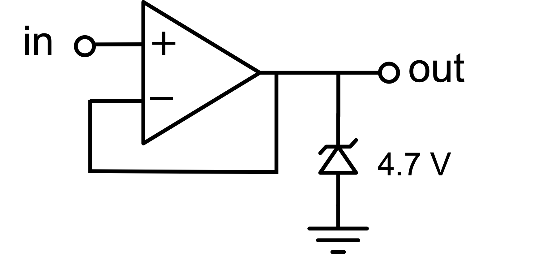
Op-Amp Follower with Zener diode to limit output voltage to below 4.7 V.
Breadboard Layout
As you start building more complicated circuits, breadboard organization makes them easier to build correctly and debug when things go wrong. As an example of moderate organization, here is my breadboard at the end of today’s exercise.
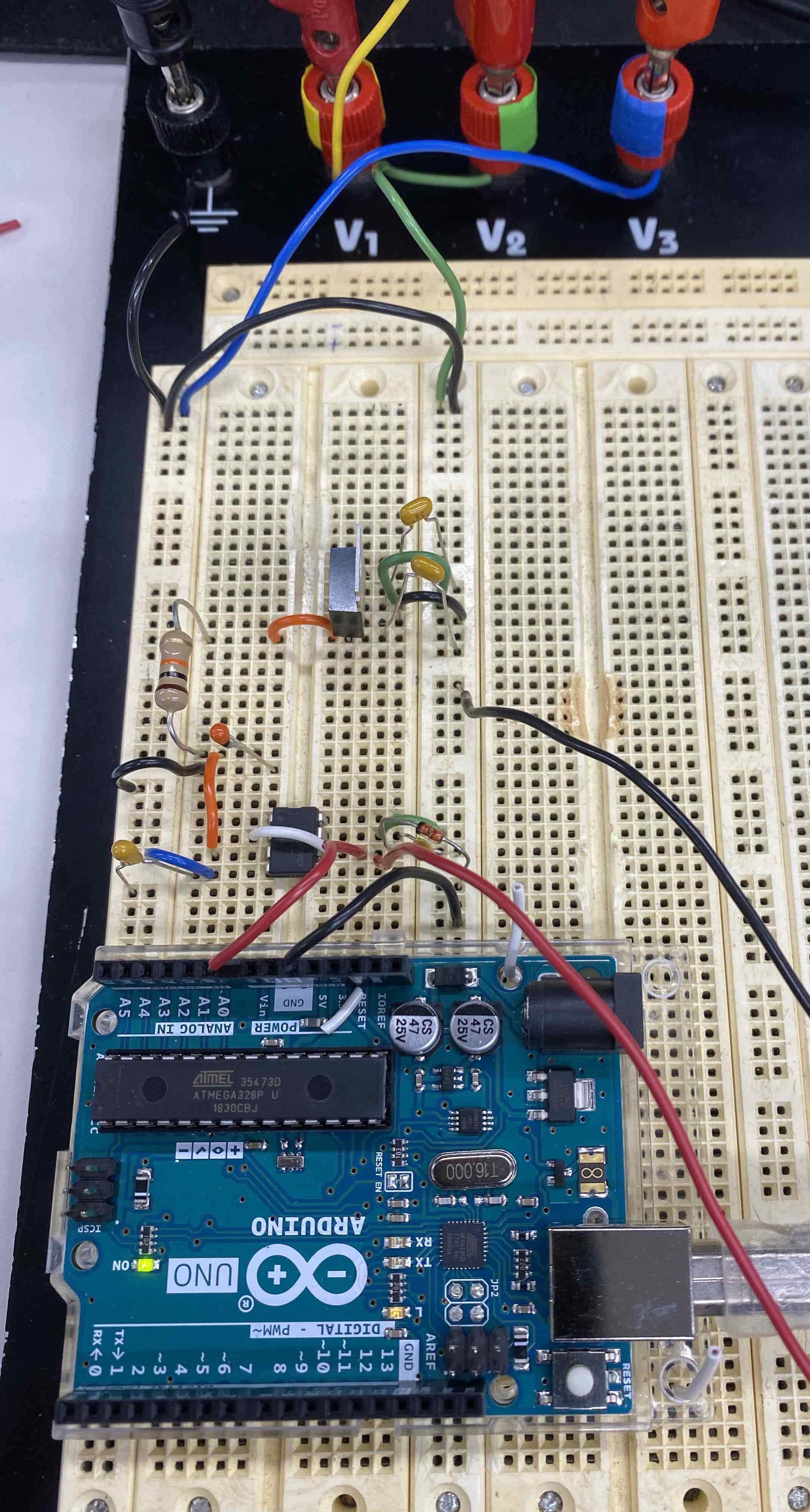
Example of Prof. Bailey’s breadboard for today’s exercise R-10.
- Use consistent colour wires. For example, my convention for this lab is:
- Black wires are Common.
- Yellow wires are DC Power Supply Output 1.
- Green wires are DC Power Supply Output 2 (\(V_{supply}^+\)).
- Blue wires DC Power Supply Output 3 (\(V_{supply}^-\)).
- White or Orange wires are internal connections.
- Red wires are Input or Output
- Use the power rails columns for the \(V_{supply}^+\) and \(V_{supply}^-\).
- Create Common rows or columns to provide easy access.
- In general it is best to only have a single Common connection for any circuit.
- I used some short white wires to hold the Arduino in place on the board.
Analog Input Test
To learn how to measure voltages using the Arduino, build this simple circuit feeding an Arduino Analog Input pin.
- Connect your LM7805 voltage regulator circuit output to a resistive divider with a 10K resistor in series with a 10K potentiometer.
- A potentiometer (or “trimpot”) is a small 3-wire variable resistor. -If a voltage is is applied across the outer two wires, the middle wire provides an output voltage that can be adjusted by rotating the slot on top with your little screwdriver.
- In this case, connect pin 1 of the trimpot to the 10K resistor and pin 2 to ground.
- A potentiometer (or “trimpot”) is a small 3-wire variable resistor. -If a voltage is is applied across the outer two wires, the middle wire provides an output voltage that can be adjusted by rotating the slot on top with your little screwdriver.
- Feed the output (from trimpot pin 1) into your zener-protected op-amp follower circuit.
- Feed the output of this op-amp circuit into pin A0 of your Arduino.
- Connect an Arduino ground (GND) pin to your circuit ground so the Arduino has a reference Common potential for the pin A0 voltage measurement.
Use the File \(\rightarrow\) Examples \(\rightarrow\) 01.Basics \(\rightarrow\) AnalogReadSerial example to read the voltage from pin A0.
- To see the output from the running sketch, click
Tools\(\rightarrow\)Serial Monitor- It is best to change the delay in the sketch from 1 to >300 so the numbers don’t scroll too fast.
- Make sure the
Autoscrollbox below the output screen is ticked.
- If pin A0 does not work, e.g. because it has been fried by applying to large a voltage, try another pin and change the sketch code accordingly.
By changing the potentiometer, you can feed various voltages into the Arduino. By measuring the input voltage with your multimeter, and comparing it to the values reported by the Arduino, measure the conversion factor between volts and the Arduino output.
R-8) Does the measured volts/bit agree with the expected value?
Arduino Temperature Measurement
Replace your potentiometer with your thermistor.
- i.e. Take voltage across thermistor reference resistor and feed it into the op amp follower and then take that (zener protected) output in Arduino Analog Pin 0
- At this point, your circuit should look similar to Figure @ref(fig:Breadboard))
Modify an Arduino program that converts the output of the thermistor circuit into temperature and prints it out on the serial port. The basic program, arduino_thermistor.ino, is available on the course resources page.
- This sketch will not run correctly “out of the box”. You need to set various parameter values: V_divider, R_fixed, A_1, B_1, C_1, D_1, and possibly others.
Use Tools \(\rightarrow\) Serial Plot to show the temperature as a function of time, while heating up the thermistor with your hand and then removing your hand to let it cool down.
R-9) Take a photo of the plot and include it in your report, noting on the photo the times when you are holding the thermistor.
- Note that the only way to stop an Arduino sketch is to replace it with another one, e.g
Blink.- This also means that the Arduino keeps running whatever sketch was last loaded into it, even if the Arduino IDE is closes, as long as the Arduino has power.
- If you connect the thermister to longer wires, it is a more useful sensor that can be brought close to sources of heat or cold.
- Note: The thermistor does not work in water, since the water conducts electricity between the thermistor’s metal leads. With Toronto tap water, this parallel resistance is very similar to the thermistor resistance.
Python Communications with Arduino
Although Serial Monitor and Serial Plot are very useful, it is generally better to to transmit data from the Arduino to our own computer where it can be stored and analyzed. We will (unsuprisingly) use Python for this.
Talking to the Arduino
Open up arduino_Serial_reader.py in your preferred python environment, e.g. Spyder, Jupyter, ….
Carefully read the instructors at the beginning of the python file. For example, you need to replace
port = '/dev/cu.usbmodem143301'
with the correct port for your Arduino, visible under the Arduino IDE Tools menu. If you have trouble identifying the correct port, you can run port_check.py to list all the operating serial ports on your computer.
- Note: If you unplug the Arduino, or reboot your computer, the port may change.
- If
pyserialis not already installed in your python environment, you will need to install it.- For Anaconda Python, look here for help on how to Add packages to Anaconda environment in Python.
- If you cannot see the ports and are using something other than Anaconda Python, the simplest solution may be to install Anaconda Python.
- In principle,
pyserialcan be installed and used with any python, but it is harder for us to help you debug problems if you are not using the standard UofT undergraduate Physics Anaconda Python.
- In principle,
Start arduino_Serial_reader.py running.
- If you get a serial port
access deniederror, it is likely that the Arduino Serial Monitor or Plotter is running and controlling the port. Closing the Arduino IDE should solve the problem and allow python to access the port. - If in Spyder you get a No module named ‘serial’ error, install pyserial by entering pip install pyserial in Spyder console.
While the python code is running:
- Warm up the thermistor with your fingers until you can see from the terminal that the temperatures has stabilized, then let go.
- Continue taking data until the temperature stabilizes again.
R-10) Include a screen capture of the resulting plot showing the rise and fall in thermistor voltage.
- The raw plot from arduino_Serial_reader.py is sufficent. It is not necessary to convert the ADC counts to volts or analyze the data to make a plot of actual temperature vs time.
End of Lab
Looking Towards Final Project
This week’s exercise could be the basis for a variety of final projects, either using the thermistor, or using similar circuits with a photodiode or piezo transducer.
Clean-up
- Properly dispose of any waste, e.g. wire or insulator cuttings
- But keep any small connector wires you may have made, they will be useful over the semester.
- If a component has been damaged, e.g. it smoked because of overheating, dispose it.
- Turn off all equipment.
See you in the next lab!