PHY405 Electronics, Lab 8
Adapted from Prof. David Bailey's website in 2022
Overview
A few circuits that are interesting and that might help with your project:
- Integrator
- Differentiator
- Buzzer
Using some components you haven’t used before:
- 555 timer
- switch
- piezo transducer
Safety Reminders (for both humans and electronics)
The DC power in this experiment comes from your DC power supply. You do not need an Arduino for this lab, so make sure none is connected to your circuit. We don’t want >5V accidentally going into (and frying) a Arduino pin by accident.
Set a current limit (e.g. 50 mA) on your DC supplies, to reduce the chance of frying miswired components.
Exercises
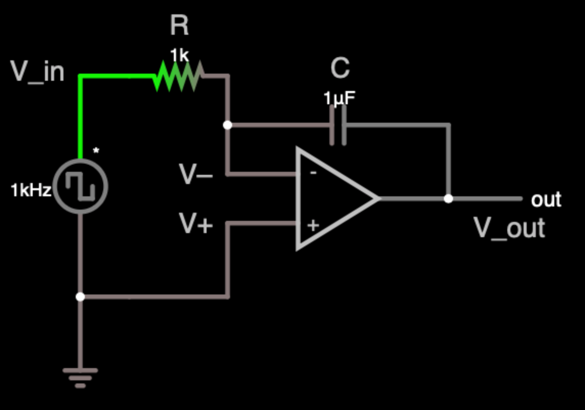
Differentiators
Simple passive RC or LR circuits can act as circuits that passively differentiate their input, i.e. \(V_{out} \propto \frac{dV_{in}}{dt}\), but op amp differentiators allow more control (with careful thought about the details of the circuit).
An ideal op amp has infinite input impedance and draws no current, so in the ideal simple circuit below, the current through the resistor and capacitor is:
\[I_C = C \frac{d\left(V^- -V_{in}\right)}{dt} = I_R = \frac{V_{out}-V^-}{R}\]
Assuming an ideal op amp, then for this circuit \(V^- = V^+ = 0\), so
\[C \frac{dV_{in}}{dt} = \frac{-V_{out}}{R}\]
\[\therefore V_{out} = - RC\frac{dV_{in}}{dt}\]

Build the above circuit on your breadboard, and play with various inputs and observe the outputs.
- You can use whichever op amp you prefer.
- Power your circuit from your DC power supply, using whichever outputs are appropriate..
R-1) If you input a 50 Hz, 1 Vpp amplitude, 0 V Offset Ramp input, is the output what you expect?
R-2) How does the output get better or worse if you put a 100nF capacitor in parallel with the 1k resistor? Can you qualitatively explain any differences?
- Changing the frequency to 1kHz may help your understanding.
- Include scope screen captures for all of the above.
Integrators
An ideal op amp has infinite input impedance and draws no current, so in the ideal simple circuit below, the current through the resistor and capacitor is:
\[I_R = \frac{V^- -V_{in}}{R} = I_C = C \frac{d\left(V_{out}-V^-\right)}{dt}\]
Assuming an ideal op amp, then for this circuit \(V^- = V^+ = 0\), so
\[\frac{-V_{in}}{R} = C \frac{dV_{out}}{dt}\]
\[\therefore \frac{dV_{out}}{dt} = -\frac{1}{RC}{V_{in}}\]
\[\therefore V_{out} (t) = -\frac{1}{RC}\int_0^t V_{in}(t')\,dt'\]
Build the above circuit on your breadboard with Wavegen input, and play with various inputs and observe the outputs.
- Monitor the input and output with Scope channels 1 & 2 respectively.
R-3) If you input a 1 kHz, 1 Vpp amplitude, 0 V Offset Square input, is the output what you expect? If not, can you explain any unexpected characteristics?
- If there are aspects of the output that you cannot explain, you may want to play around more with various inputs and outputs.
- For example, what happens if you change the Wavegen Offset from 0 to +10 mV or -10 mV?
The above simple integrator is not a practical circuit because it is sensitive to even tiny DC offsets on the input or non-zero currents flowing through the op amp. To improve the circuit we can try:
- shorting out any DC offset to ground at the input of the op amp, or
- shorting out any DC offset to ground at the output of the op amp, or
- adding DC feedback in parallel to the capacitor’s AC feedback, or
- blocking DC on the output.
R-4) Which of above solutions most improves the output of your circuit?
- “improves” is somewhat subjective, so justify your answer.
- Limit yourself to just one component at a time, either L, C, R.
- Clearly specify the added component and where it is added.
- Include scope screen captures as needed.
Timer
The LM555CN is one of the family of 555 timer chips.
- See the lecture for more information on 555 timers and piezos.
Build the circuit in Figure 6-5 of the NE555P Spec Sheet, with nominal \(R_A=330k\), \(R_B=100k\), and \(C=47nF\).
- \(R_L\) can be left out, i.e \(R_L=\infty\)
- Measure the actual values of any resistors and capacitors before inserting them in your circuit.
- Duty cycle for a square wave is one of your scope measurement functions, which can save a bit of time.
R-5) Include a screen capture of the output.
R-6) Try a few different resistors and capacitors to confirm that the frequency and duty factor change as expected according to the relations following Figures 6-5 and 6-6 on page 12 of the NE555P Specifications.
Buzzer
Let’s expand the above circuit into a tunable, battery powered, push-button buzzer. Build this circuit.

Notes:
- “R_fake” is not a real component to be included in your circuit. It is just avoid a “Capacitor loop with no resistance!” error in the simulation.
- If your simulation slows down when you push the switch, restarting the simulation with RUN/Stop should speed it back up.
- If you chose to use a low-power 6004 op amp for earlier exercises, make sure you do not accidentally put 9V into its power pins. It is only rated to 6V.
- Use a 9V Battery Snap Connector to connect to the 9V cell. (Negative terminal of the battery to Common, positive terminal to the circuit’s DC power.)

The piezo connector wires may be too soft to insert into the breadboard sockets, so you may want wrap them around some small jumper wires inserted in the sockets. (Soldering the wrapped joins would be best, but is probably not neccessary for this temporary circuit.)
Connect the piezo to the output and confirm that it buzzes when the button is pressed.
Replace one of the resistors with a 100k trim-pot, and confirm that the buzzer frequency changes as the trim-pot resistance is changed.
- Choose the resistor to replace based on getting the widest frequency range and better (i.e. closer to 50%) duty factor for better sound.
R-7) Explain why you chose that resistor to change and not the other.
R-8) Make a short (<30s) video with audio, showing your push button buzzer circuit working.
- Disconnect any external connections from the circuit for the video.
- The video should show the complete circuit with
- all components (including batter) visible
- the buzzer going on and off as you press the button on the switch.
- the pitch (frequency) changing as you adjust the trim-pot resistance with your little screwdriver.
- If you don’t have a partner and need a hand with the video, ask the Prof, TA, or another student for help.
End of Lab
Looking Towards Final Project
This is the last regular lab. Next week you are working on your project.
Once again this week’s exercise could again be the basis for a final project.
For example, for the buzzer, could you:
- add volume control?
- make the output more sinusoidal and otherwise improve the output sound quality?
- add an LED “colour organ” where different colour LEDs would light up depending on frequency?
- use the piezo as a sensor with LEDs that light up depending on the amplitude or frequency of the sense vibrations?
- …
Clean-up
- Properly dispose of any waste, e.g. wire or insulator cuttings
- But keep any small connector wires you may have made, they may be useful in future.
- If a component has been damaged, e.g. it smoked because of overheating, dispose it.
- Turn off all equipment.
See you next week!