

|
 Alan Stummer
Research Lab Technologist |

Analog Isolator
Downloads
|
I am curious who uses what. Are these webpages a waste of time, or are they any help to others? Are the circuits, software and utilities appearing in other labs? Please send your comments or suggestions or what you have used (or not) or schematics of your version or pictures or anything! Email me, or be creative and send a postcard!I want to hear from the vacuum! |
Links
|
|
||
|
NOTICE: This webpage and associated files is provided for reference only. This is not a kit site! It is a collection of my work here at the University of Toronto in the Physics department. If you are considering using any schematics, designs, or anything else from here then be warned that you had better know something of what you are about to do. No design is guaranteed in any way, including workable schematic, board layout, HDL code, embedded software, user software, component selection, documentation, webpages, or anything. All that said, if it says here it works then for me it worked. To make the project work may have involved undocumented additions, changes, deletions, tweaks, tunings, alterations, modifications, adjustments, waving of a wand while wearing a pointy black hat, appeals to electron deities and just plain doing whatever it takes to make the project work. |
||

 Started October 2010 for
Joseph's lab. This is an effort to reduce the amount of smoke and vapourized copper caused by unintentional
extra grounds in high current systems. It provides full galvanic isolation between the input and output
sides with unity gain over ±10V. It is specifically aimed at power supply and coil control. For
example, HP/Agilent supplies are [in]famous for referencing the control inputs for voltage and current to the
supply's positive output, while traditionally the negative output is held around ground potential.
Started October 2010 for
Joseph's lab. This is an effort to reduce the amount of smoke and vapourized copper caused by unintentional
extra grounds in high current systems. It provides full galvanic isolation between the input and output
sides with unity gain over ±10V. It is specifically aimed at power supply and coil control. For
example, HP/Agilent supplies are [in]famous for referencing the control inputs for voltage and current to the
supply's positive output, while traditionally the negative output is held around ground potential.
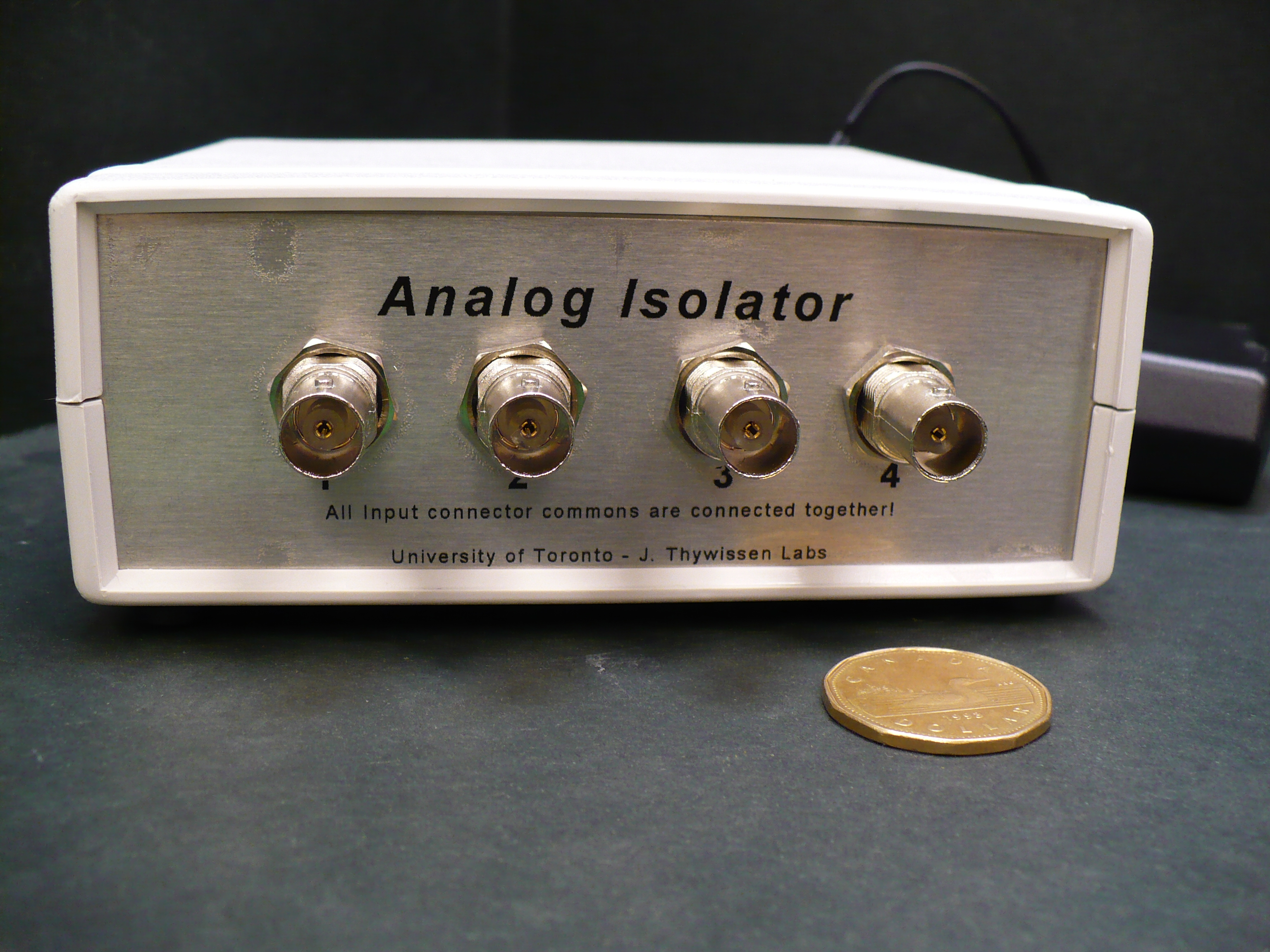
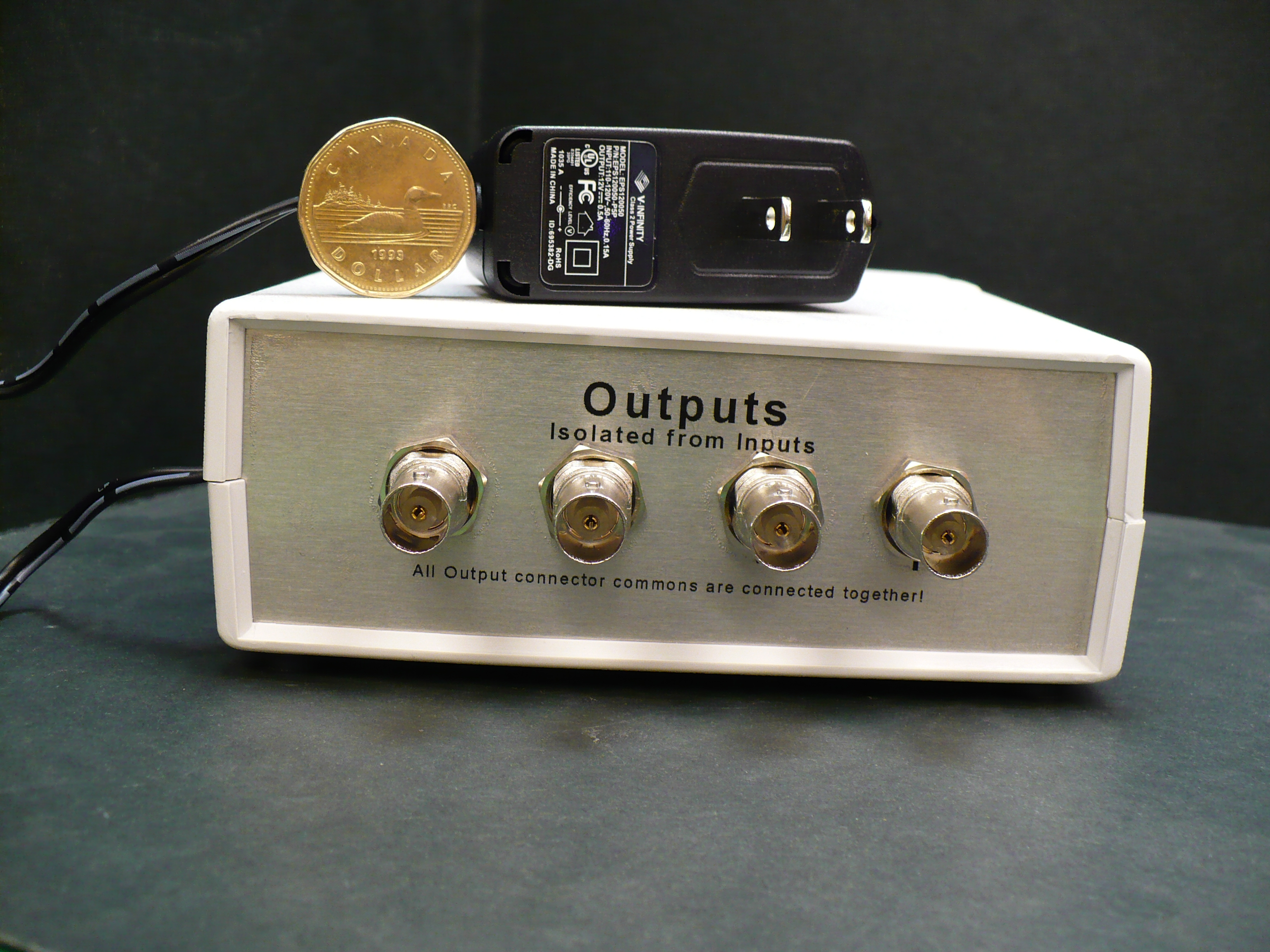
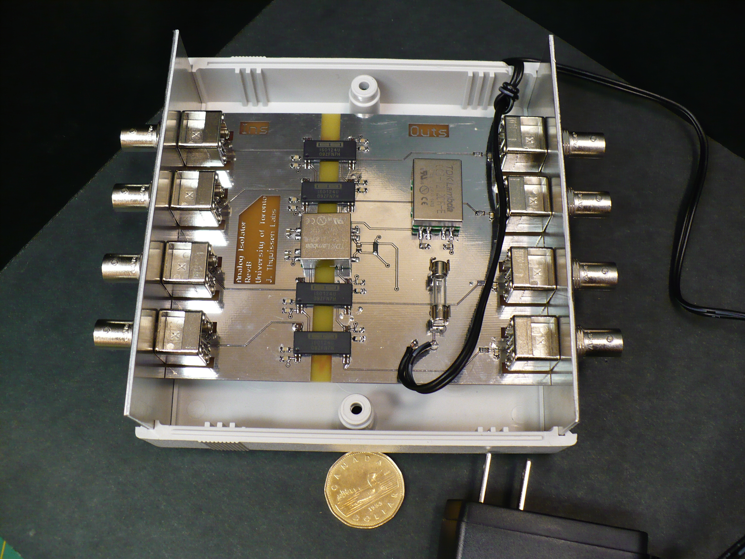
There are two versions: the origianl with two channels and the next with four. Input commons are all connected together, output commons are connected together but input and output commons are isolated. In other words, although the inputs are floating from the outputs, the inputs' common connection are shared and similarly for the output side. Power is from a 12/15V wall wart. The 12/15V is converted to ±12/15V for both the input and output sides by separate 1W DC-DC converters. Although not necessary, both sides are isolated from the wall wart, which is isolated from the AC line.
The heart of the isolation is the isolator. Two methods were considered: Avago's HCNR20x series of analog optocouplers, and, T.I.'s ISO12x series of isolation amplifiers. The former is faster and lower noise and messy to make bipolar, the latter is simpler (less parts) and has better offset and inherently bipolar. The dart board and some consideration selected the latter.
Parameters
| Absolute Maximums | ||||
| Parameter | Conditions | Min | Typ | Max |
| Input | Continuous | 25V | ||
| Isolation | Continuous | 500V | ||
| Electrical Characteristics | ||||
| Input Voltage | -10V | +10V | ||
| Output Voltage | -10V | +10V | ||
| Input Resistance | 200K Ohm | |||
| Output Offset | 25°, spec | ±20mV | ±50mV | |
| Measured | +20.5mV & +12.5mV | |||
| Noise, measured | to 20MHz | 16mV p-p, 1.2mV Rms | ||
| Noise, measured | Fundamental | 1KHz dominant | ||
| Error, measured | ±8Vp-p | 180mV approx | ||
Screen Captures

Figure 1. Sample noise capture, 20MHz BW
|

Figure 2. Sample transfer and [quantized] error |
Figure 3. In-Out transfer curve
|
Return to homepage
| Sorry, no more chance for asking direct questions, queries, broken links, problems, flak, slings, arrows, kudos, criticism, comments, brickbats, corrections or suggestions. |
|

|