

|
 Alan Stummer
Research Lab Technologist |
|
|
General Purpose DDS |
|

Downloads
|
I am curious who uses what. Are these webpages a waste of time, or are they any help to others? Are the circuits, software and utilities appearing in other labs? Please send your comments or suggestions or what you have used (or not) or schematics of your version or pictures or anything! Email me, or be creative and send a postcard! I want to hear from the vacuum! |
Links
|
|
NOTICE: This webpage and associated files is provided for reference only. This is not a kit site! It is a collection of my work here at the University of Toronto in the Physics department. If you are considering using any schematics, designs, or anything else from here then be warned that you had better know something of what you are about to do. No design is guaranteed in any way, including workable schematic, board layout, HDL code, embedded software, user software, component selection, documentation, webpages, or anything. All that said, if it says here it works then for me it worked. To make the project work may have involved undocumented additions, changes, deletions, tweaks, tunings, alterations, modifications, adjustments, waving of a wand while wearing a pointy black hat, appeals to electron deities and just plain doing whatever it takes to make the project work. |
||

Overview
Started March 2011 for Joseph's lab. Previous projects have included DDSs for evaporation, microwave generation, RF phase manipulation and miscellaneous purposes. This project is not for any specific experiment but is a general lab instrument. It is back-compatible with existing ADwin software used in the Thywissen labs. The core of the project is an Analog Device's AD9910 1GSPS 14-bit DDS. Rather than make a complete DDS board, the AD9910 eval board is used.
Nomenclature: "Host" is the the controliing computer. "Unit" is the GP DDS project. "Rabbit" is the Rabbit controller module in the unit.
As mentioned above, it is fully compatible with existing software for the ADwin used in the Thywissen labs. There is a new command: Wait for the ramp to finish before executing the next command in the command sequence. This is useful for segmented non-linear ramps. If this command is inserted between segments, each segment will finish ramping then the next segment will start. See this document for details.
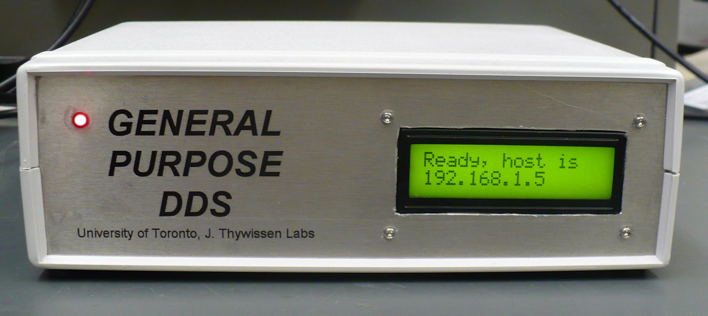
As mentioned above, all user control is via the user interface on the host computer. First, plug the ethernet connector on the back of the unit into a switch, hub or NAT router on the same subnet as the host. Turn it on. The unit will show you its name, static IP address and port. Your host must connect to that address and port using UDP. Several units may be on the same subnet, each will have a unique IP address. For security reasons, every time the unit is turned on, the first host to connect to it will be the only one allowed to connect to it. To change host computers, the unit's power must be cycled. Note the red LED on the front. When it turns on, the precision frequency reference is stable. This should happen within a minute.
Connect a coax to the RF output on the back. As with all RF work, it must be properly terminated with 50 Ohms. No harm will result if improperly terminated but reflections up and down the cable may cause the output amplitude to vary.
Three BNC outputs on the back can be used for verification or debugging. They are TTL level, do not short the outputs. Q1 "Update" pulses high during frequency changes and ramp starts, Q2 "Ramping" is high while a ramp is in progress, Q3 "Running" is high while the command sequence is running. Two spare BNC inputs are provided for future use. As with the Trigger input, they are TTL level.
There is a test GUI (Graphical User Interface program) written in VB6. It can be used as a guide for writing your own host program in any language you like.
The host computer sends commands to the unit to control it. The structure for these commands are available in this document . Commands can be either sent one at a time (one per UDP packet) or concatenated and sent in one or more packets. There are three categories of commands, as follows:
-
Heartbeat: This command is not necessary but is useful to know when the unit is alive and well. Send the Heartbeat command and the unit will echo it back. Repeat this every second or so. If no command or heartbeat reaches the unit after about two seconds, it assumes the host is gone. This is harmless, only the display is dimmed. If the host does not receive an echoed heartbeat after about two seconds then the host can assume the unit is offline (powered off or an ethernet issue) and stop the experiment. Without heartbeats, the host may send commands which are never implemented.
-
Immediate Commands: There are two immediate commands: set a frequency and start a ramp. Setting a frequency is simple because the only parameter is the frequency. Can't miss. Resolution is <1Hz, Nyquist frequency is 500MHz, best to stay well below Mr Nyquist. A ramp is pseudo linearly moving from the current frequency to another frequency over time. The slope, or rate of frequency change, is set by two parameters: step size and step rate. Step size is <1Hz resolution, step rate is in 4nS increments. The optimal settings will give a smooth ramp.
-
Command Sequence: This is the raison d'etre of the project. A series of commands are loaded into the unit and then executed in sequence. The command string sent from the host is prefaced with an 0xA4 byte. The unit knows not to run the following command but to store it in the command sequence. Commands stored in the command sequence can be to set a frequency, start a ramp or wait for a Trigger input before executing next command in the command sequence. The first two - set a frequency or ramp - are exactly like doing this in as an immediate command. The latter - wait for Trigger before proceeding - will tell the unit to wait for a rising edge on the TTL level BNC input jack on the back of the unit. This allows frequency steps or ramps to occur at externally controlled times.
How to do non-linear ramps: Use a series of short linear ramps. Into the command sequence, load a short ramp segment followed by a Wait For Trigger command, then the next short ramp segment and a Wait For Trigger command, etc etc. Start executing the command sequence and send a trigger pulse after each ramp.
Frequency Tuning Word (FTW) calculation: The output frequency is related to the system clock, which is 1GHz. The basic equation - from P23 in the DDS manual - is:
Example of setting 1MHz output: Refering to the document showing the command protocols structure, make a command string. First, calculate the FTW for 1MHz. Using the above equation, FTW is 4.294967296 * 10 6 in base 10, or 32-bit hex 0x00418937. Now build the 6-byte command string.
byte 2: 0x00 Don't care, used for back compatibilty with old software for the Thywissen labs
byte 3: 0x37 The LS (least significant) byte of the FTW as calculated above
byte 4: 0x89
byte 5: 0x41
byte 6: 0x00 The MS byte of the FTW
Example of command sequence to step to 1MHz then ramp to 100MHz: Refering to the document showing the command protocols structure, make the command strings.
- Calculate the FTW for 1MHz. Using the above equation, FTW is 4.294967296 * 10 6 in base 10, or 32-bit hex 0x00418937.
- Calculate the FTW for 100MHz. Using the above equation, FTW is 0x1999999A.
- Calculate frequency slope by setting the 32-bit step size and the 16-bit step time. This is subjective depending on required smoothness and accuracy: small time steps or small frequency steps or a mix? Time steps are fixed at multiples of 1/10 9Hz = 4nS, frequency steps are fixed at multiples of 1/4.294967296 = 0.2328306437. Let's use numbers selected by a dart board: 2 for time step and 95 for frequency step. Converted to hex, these are 0x0002 for time and 0x0000005F for frequency. These random numbers work out to (95*0.233...Hz)/(2*4nS) = 2,764,863,893Hz/Sec, or 27.928 seconds for the 99MHz ramp from 1MHz to 100MHz. Very slow but good as an example. Note that the ramp will never overshoot. For example, if you ramp from 10MHz to 15MHz in coarse 3MHz steps, the frequencies will be 10MHz, 13MHz then 15MHz.
- Make the command string, either one command per UDP packet, or all in one packet, or anything in between as long as each command is complete in any one packet. Don't split any one command between two packets!
...add to set the initial frequency:
byte 2 (1): 0xC1 Add following command to command sequence (note that this is the start of a complete command, ends with byte 8)
byte 3 (2): 0xA5 The command to set the frequency by setting the FTW
byte 4 (3): 0x00 Don't care, used for back compatibilty with old software for the Thywissen labs
byte 5 (4): 0x37 The LS (least significant) byte of the FTW for 1MHz as calculated above
byte 6 (5): 0x89
byte 7 (6): 0x41
byte 8 (7): 0x00 The MS byte of the FTW
...add to wait for a Trigger before proceding:
byte 9 (1): 0xC1 Add following command to command sequence (note that this is the start of a complete command, ends with byte 10)
byte 10 (2): 0xA4 Wait for a Trigger input before executing next command
...add the ramp:
byte 11 (1): 0xC1 Add following command to command sequence (note that this is the start of a complete command, ends with byte 27)
byte 12 (2): 0xAC The command for setting a frequency ramp
byte 13 (3): 0x00 Don't care
byte 14 (4): 0x00 Don't care
byte 15 (5): 0x5F Ramp step size, LS byte
byte 16 (6): 0x00
byte 17 (7): 0x00
byte 18 (8): 0x00 Ramp step size, MS byte
byte 19 (9): 0x00 Don't care
byte 20 (10): 0x02 Ramp rate, LS byte
byte 21 (11): 0x00 Ramp rate, MS byte
byte 22 (12): 0x00 Don't care
byte 23 (13): 0x00 Don't care
byte 24 (14): 0x9A Stop FTW, LS byte
byte 25 (15): 0x99
byte 26 (16): 0x99
byte 27 (17): 0x19 Stop FTW, MS byte
...and now to execute the saved commands:
byte 28 (1): 0xC4 Execute the saved commands
byte 29 (2): 0x00 Dummy byte.
This project is an update of the DDS section of the ChromaMatic2 project. It resolves the latency issue from the Rabbit processor receiving the trigger signal (to go to the next saved frequency or ramp) sent from the ADwin realtime controller. This is done by adding an FPGA between the Rabbit and the DDS. Before the experiment is run, the Rabbit receives the command list from the host PC. These are transferred into the FPGA. The ADwin's trigger signal goes directly to the FPGA which then parallel loads the command into the DDS. A list of the host commands is given in the text document " All About GP DDS.txt". This file also contains further info about the communications between the Rabbit and FPGA.
The following info is not needed by anyone developing a host interface for this project. Stop here if you don't care how the unit works. Continue if you do. All DDS commands come from the FPGA. All of these FPGA commands come from the Rabbit. These latter uses two methods: the FPGA simply pipes certain Rabbit pins to certain DDS pins and allows the Rabbit to directly control the DDS, and, the Rabbit loads commands into a FIFO in the FPGA then allows the FPGA to execute those commands by sending them to the DDS with conditions. This latter method is the real raison d'etre of using FPGA. This is called the command sequence. Details of the command sequence is given in the above document with further info in the Verilog and Dynamic C source code. Regarding the DDS, it is always run in DR mode. Single frequencies are generated by setting upper and lower FTWs apart by one LSB. Ramps are generated differently for up and down ramps. An up ramp (the target frequency is higher than the current frequency) is done by setting the lower FTW to the current FTW and the upper FTW to the target FTW and setting the two rates then implementing the registers with the IOupdate pin and ramping up. A down ramp is messier. The upper FTW is set to the current and the lower FTW to the target FTWt. The up rates are set to ramp between the limits in 4nS while the down rates are set to the commanded rate. The IOupdate pin is toggled and the ramp virtually steps to the upper limit, then the ramp direction is set to go down and the expected down ramp occurs.
Return to homepage
| Sorry, no more chance for asking direct questions, queries, broken links, problems, flak, slings, arrows, kudos, criticism, comments, brickbats, corrections or suggestions. |
|

|