

|
 Alan Stummer
Research Lab Technologist |

|
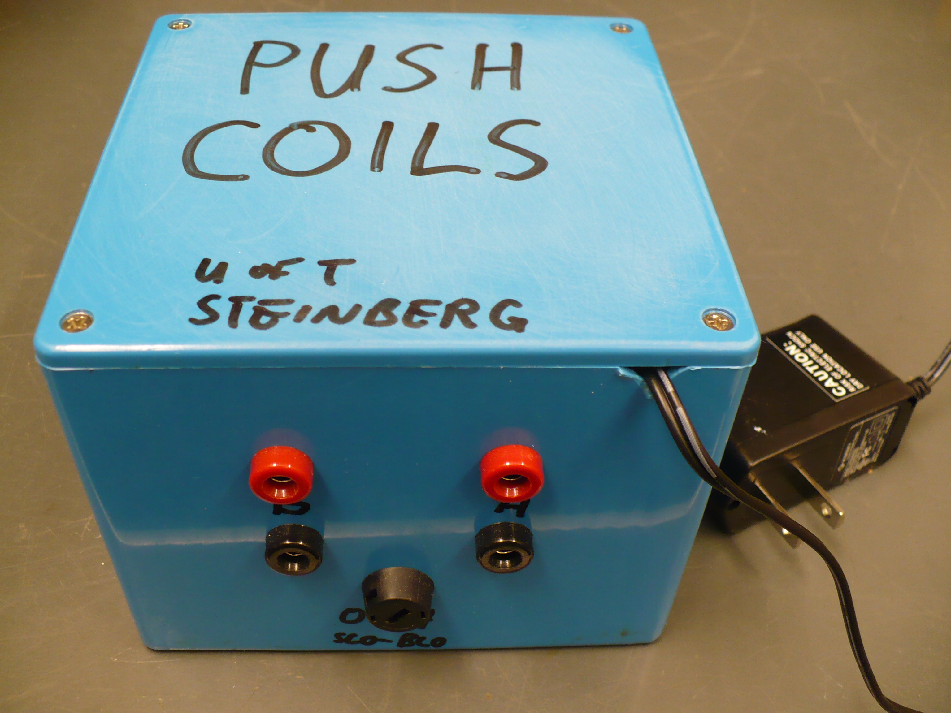
Push Coils |
|
Downloads
|
I am curious who uses what. Are these webpages a waste of time, or are they any help to others? Are the circuits, software and utilities appearing in other labs? Please send your comments or suggestions or what you have used (or not) or schematics of your version or pictures or anything! Email me, or be creative and send a postcard! I want to hear from the vacuum! |
Links
|
|
NOTICE: This webpage and associated files are provided for reference only. This is not a kit site! It is a collection of my work here at the University of Toronto in the Physics department. If you are considering using any schematics, designs, or anything else from here then be warned that you had better know something of what you are about to do. No design is guaranteed in any way, including workable schematic, board layout, HDL code, embedded software, user software, component selection, documentation, webpages, or anything. All that said, if it says here it works then for me it worked. To make the project work may have involved undocumented additions, changes, deletions, tweaks, tunings, alterations, modifications, adjustments, waving of a wand while wearing a pointy black hat, appeals to electron deities and just plain doing whatever it takes to make the project work. |
||

Overview
Started January 2012 for Rockson Chang in Aephraim's group. This project is very similar to the Magnetic Field Gradient Generator project except five time the current. A pair of anti-Helmholtz coils create a magnetic gradient for the MOT experiment. Each coil can run at up to 50A for up to 10mS, independantly controlled by a 0V to -10V control signal, scaled at 5A/V. Their fields will offset the MOT, exerting a force on it.
For the record, the Z-coil was measured at 1.5A to have a resistance of 0.28Ohms. Static inductance is 30uH, using a Meterman 37XR inductance meter.
The two channels driving the coils are identical and independant, except for sharing the +24V supply. An opamp sums the negative control voltage to a Caddock SR20-0.020-1% 20mOhm current sense resistor. The opamp input common mode voltage includes the negative rail. A IRF IRFP4468 N-FET on its output drives the coil in common source configuration with a low side current sense resistor. Because the coils are low duty cycle and only pulsed, no heatsinking is required for the FETs. The shared power supply is a 24V 0.25A wall wart. That supply charges an array of 2.5F supercap set up in series/parallel as 1.5F/25V. The supercap array handles the pulse current, losing only ~0.35V worth of charge per pulse.
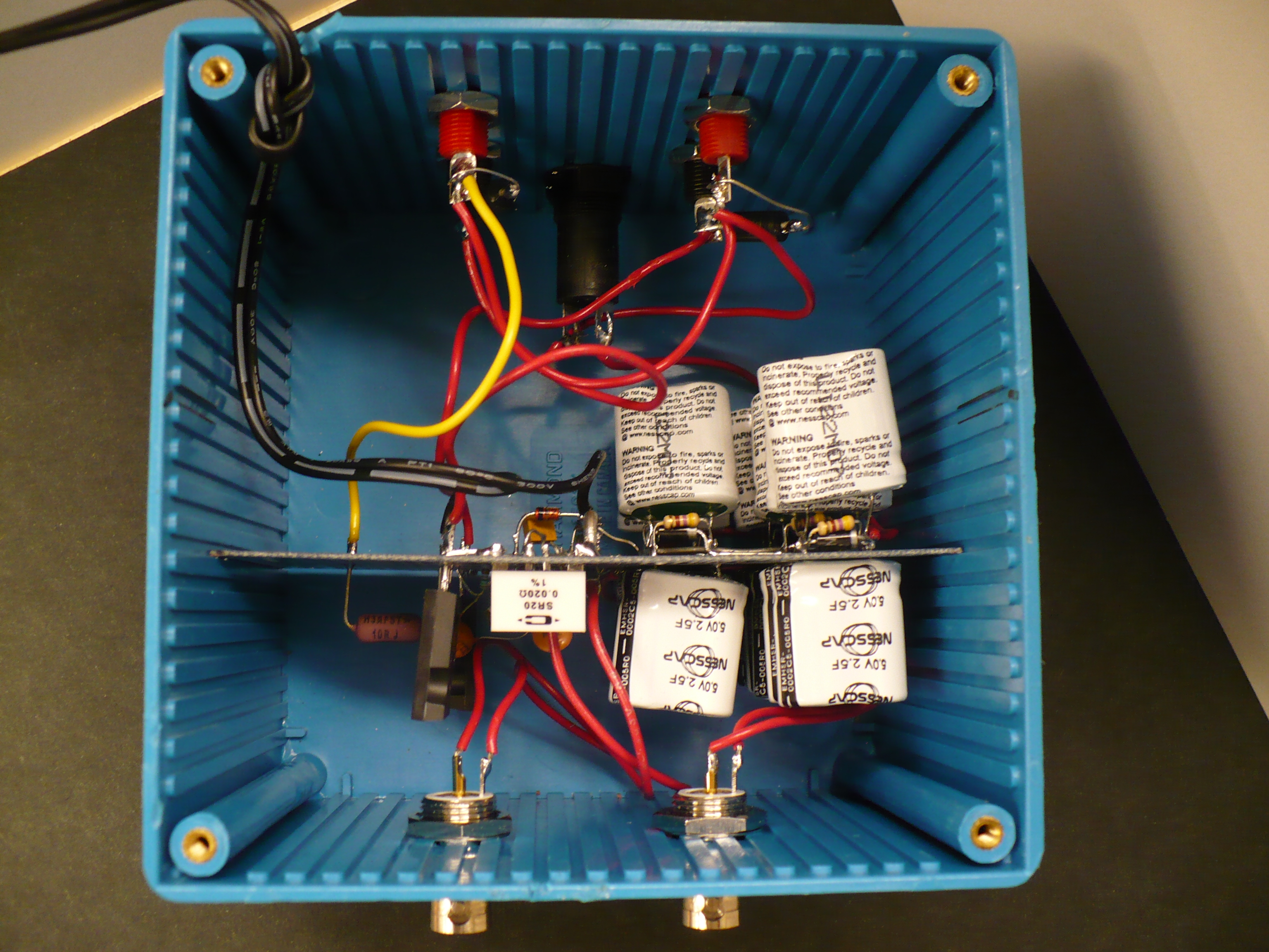
Because of the evolving requirements, the circuit is hand assembled on a
prototype board inside a plastic box.
An array of supercaps provides the pulse current. It is made from 15 of Nesscap EMHSR-0002C5-005R0 supercaps. They are 2.5F at 5V max with 65mOhm(max) ESR. Groups of three are put in parallel, five groups are put in series. Total array ratting is 1.5F/25V. Each set of three is bypassed by a 5.1/5% zener for charge and discharge balancing, and 470 Ohms for further balancing and a one hour RC discharge. The array is charged by a 24V/0.25A SMPS wall wart with current limiting and short circuit shutdown, in series with 10 Ohms. Measured from zero voltage, the array slowly charges for 10-20 seconds to about 1V before the SMPS fully kicks in at 400mA for 60 seconds then the 15 second charging RC time constant tops up the remainder. It is suggested to let the array charge for several minutes before use at full current to let the array reach 24V.
The supercap array holds 430J charge, a typical AAA battery holds about 3,000J. However, this array can put out 100 times more pulse current and 1,500 times the pulse power. Each 50A 10mS pulse uses 12J which is replenished by the wall wart.
The FETs are not heatsunk. They dissipate high power for a short period at a low duty cycle. Increasing the pulse width or decreasing the duty cycle will increase the FETs' junction temperature until they may fail. For example, a 100mS pulse will cause damage. Beware of ground loops! The coils cannot be connected to anything but the box. There is a lot of power available from the supercap array and connecting the coils incorrectly or grounding any part of the circuit other than the BNC control inputs will cause damage to the circuit and/or external equipment.
Return to homepage
| Sorry, no more chance for asking direct questions, queries, broken links, problems, flak, slings, arrows, kudos, criticism, comments, brickbats, corrections or suggestions. |
|

|