

|
 Alan Stummer
Research Lab Technologist |
|

|
Triple Coil Driver |

|

Downloads
|
I am curious who uses what. Are these webpages a waste of time, or are they any help to others? Are the circuits, software and utilities appearing in other labs? Please send your comments or suggestions or what you have used (or not) or schematics of your version or pictures or anything! Email me, or be creative and send a postcard! I want to hear from the vacuum! |
Links
|
|
NOTICE: This webpage and associated files are provided for reference only. This is not a kit site! It is a collection of my work here at the University of Toronto in the Physics department. If you are considering using any schematics, designs, or anything else from here then be warned that you had better know something of what you are about to do. No design is guaranteed in any way, including workable schematic, board layout, HDL code, embedded software, user software, component selection, documentation, webpages, or anything. All that said, if it says here it works then for me it worked. To make the project work may have involved undocumented additions, changes, deletions, tweaks, tunings, alterations, modifications, adjustments, waving of a wand while wearing a pointy black hat, appeals to electron deities and just plain doing whatever it takes to make the project work. |
||

This is only partially my design. The circuit was given to me, I made minor changes, laid out the PCB and packaged the project. No in depth analysis of noise, stability, drift, temperature sensitivity or any other parameters have been done by me but may have been done before. For information about this project please contact the student or post-doc.
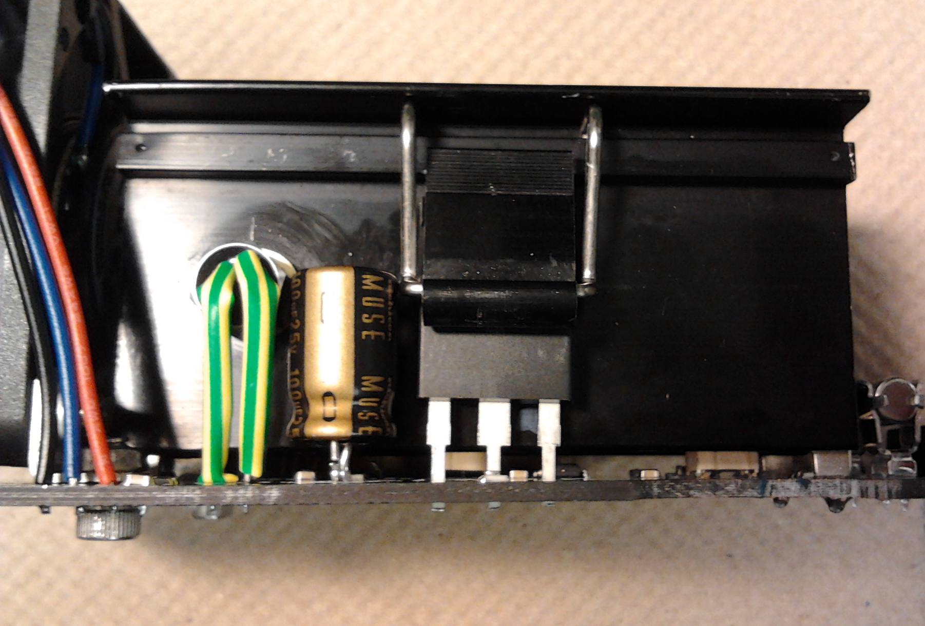
Started 2014 January for Stefan Trotsky in Joseph's lab. It is based on a circuit used in Germany and recently in Joseph's lab. Three coils adjust the ambient magnetic field, both compensating for the earth's field (and it fluctuations) and desired magnet null position. Each coil is approximately (measured) 1 Ohm and 6mH, current is normally up to ±3A but can be extended to ±10A in future. Each coil is controlled by a module.Three modules share a case with a motherboard containing power distribution and overtemperature shutdown. The modules are identical, except possibly for the pot settings, and are otherwise interchangable.
Adjustments are necessary because the coils are unkown and differ one to the other. Using a setting that works on all coils may be unnecessarily slow on some coils and fast on others. There are two adjustments per module: damping and bandwidth (BW). How they are set up depends on what you want.
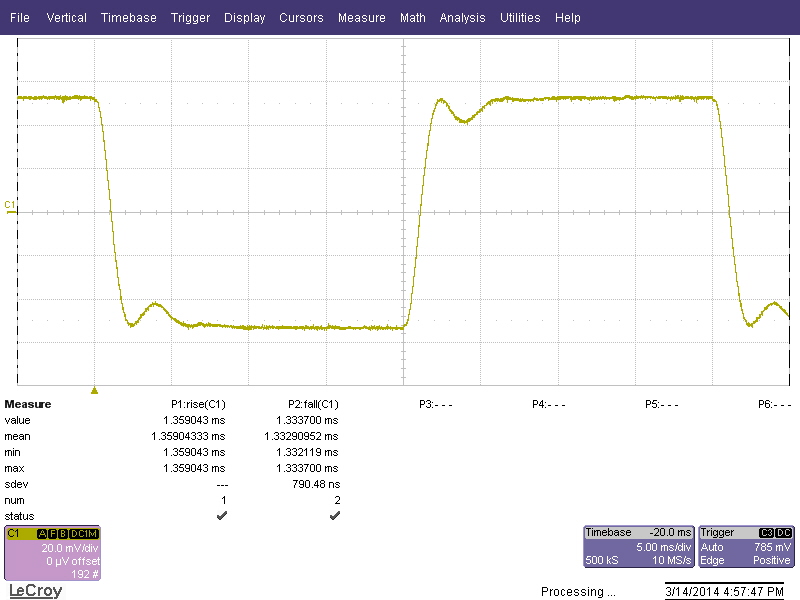
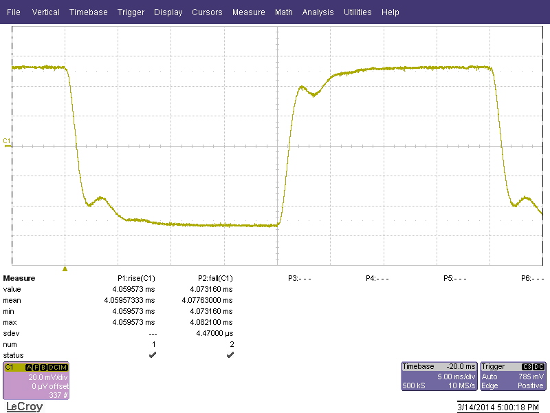
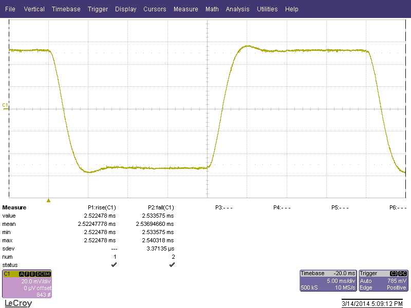
Step Response: If the damping (overshoot or undershoot) is important then adjust with a low frequency square wave. I use an input of 25Hz and ±250mV. Monitor the current at the "CURRx" test point with a scope. Because the signal is small it will probably have to be averaged to reduce the noise. Back off the BW pot (the pot nearer the fan) to about 25% from the CCW end, then adjust the damping pot (the trimpot closest to the fuse) for underdamped, critically damped or overdamped. See the screen captures below.
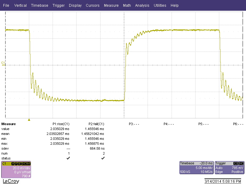
Frequency Response: If the frequency response is important then set up a signal generator for sweeping. I use ±250mV, sweep 20Hz to 1.5KHz linearly in 1 second. The other simpler option is to adjust both the damping and BW pots for critical damping and no oscillations. Notice on the "Bandwidth too high" screen capture that there are little harmonic oscillations after the steps, these can be removed by reducing the bandwidth pot.
Underdamped
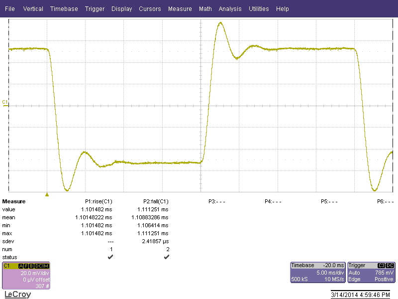
|
Critically damped
|
Overdamped
|
Bandwidth too high
|
Good bandwidth

|
Bandwidth too low (note slopes)
|
Changing a Module: Modules plug into the motherboard with a single 12-pin connector. To change a module, TURN OFF THE POWER! then unscrew the mounting on the fan side and slide out the module.
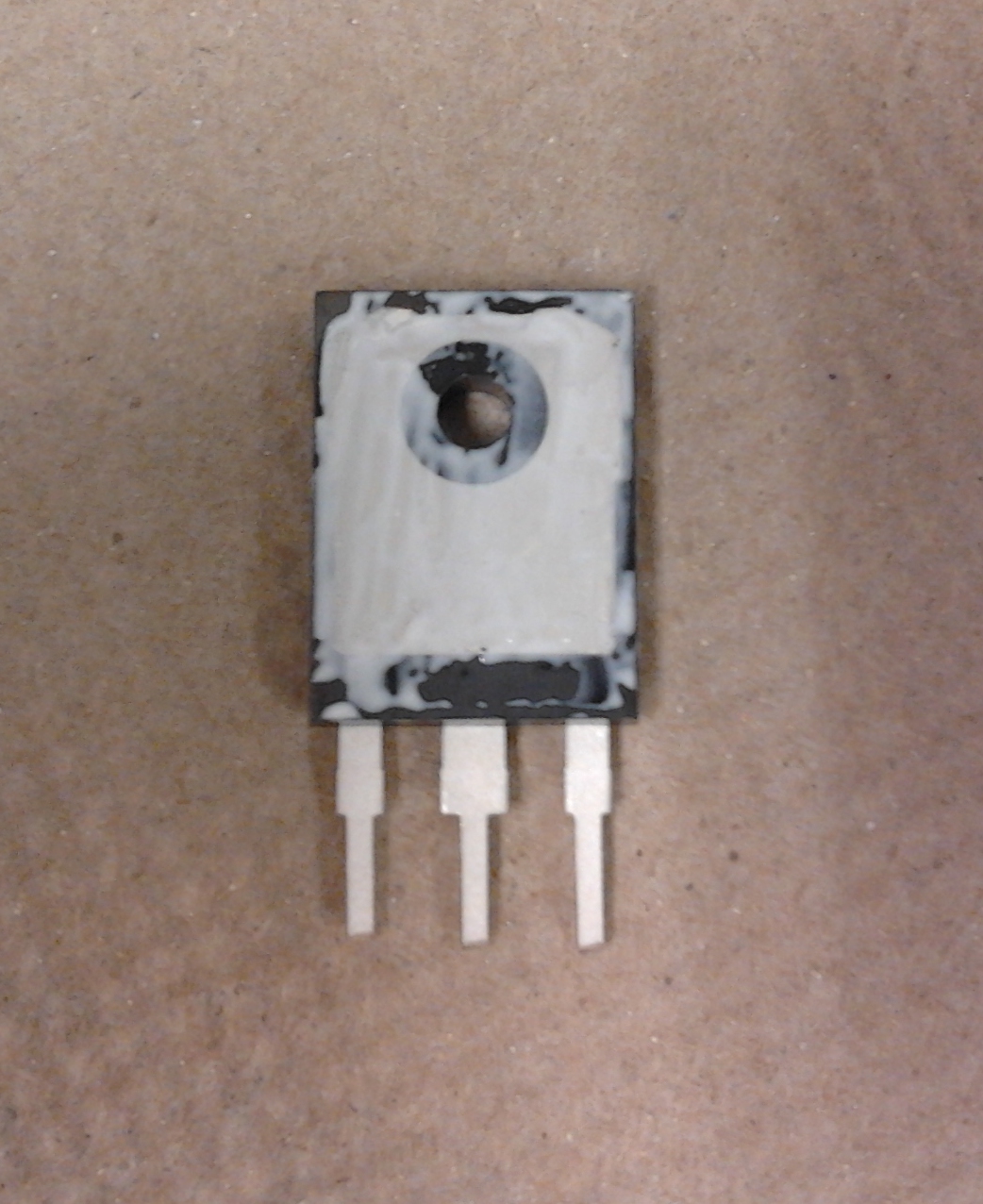
Changing a Transistor in five easy steps: The power BJTs ( Bipolar Junction Transistor) are not very static sensitive. They are from ON Semiconductors (formerly Motorola), NPN is MJH6284 (Digikey.ca MJH6284GOS-ND) and PNP is MJH6287 (Digikey.ca MJH6287GOS-ND).
|
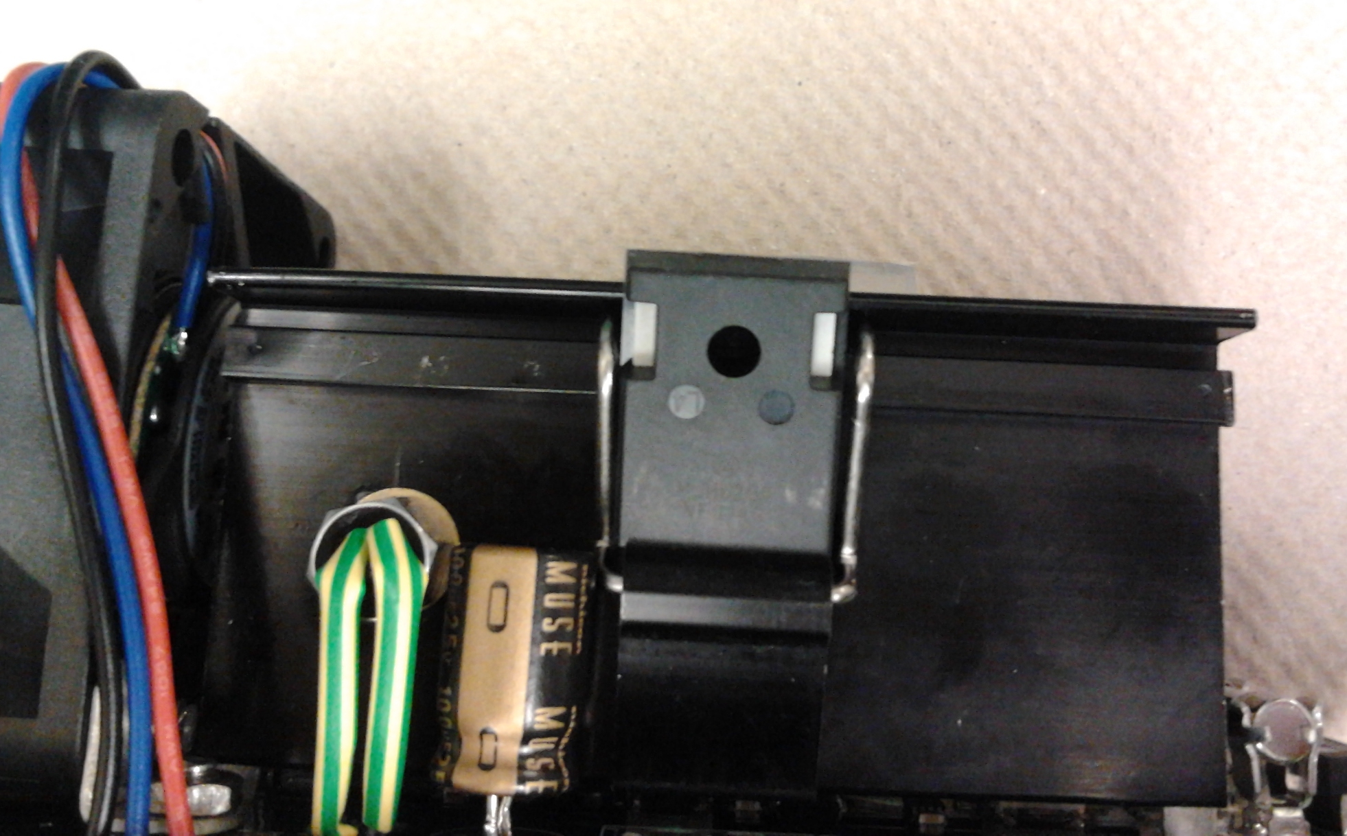
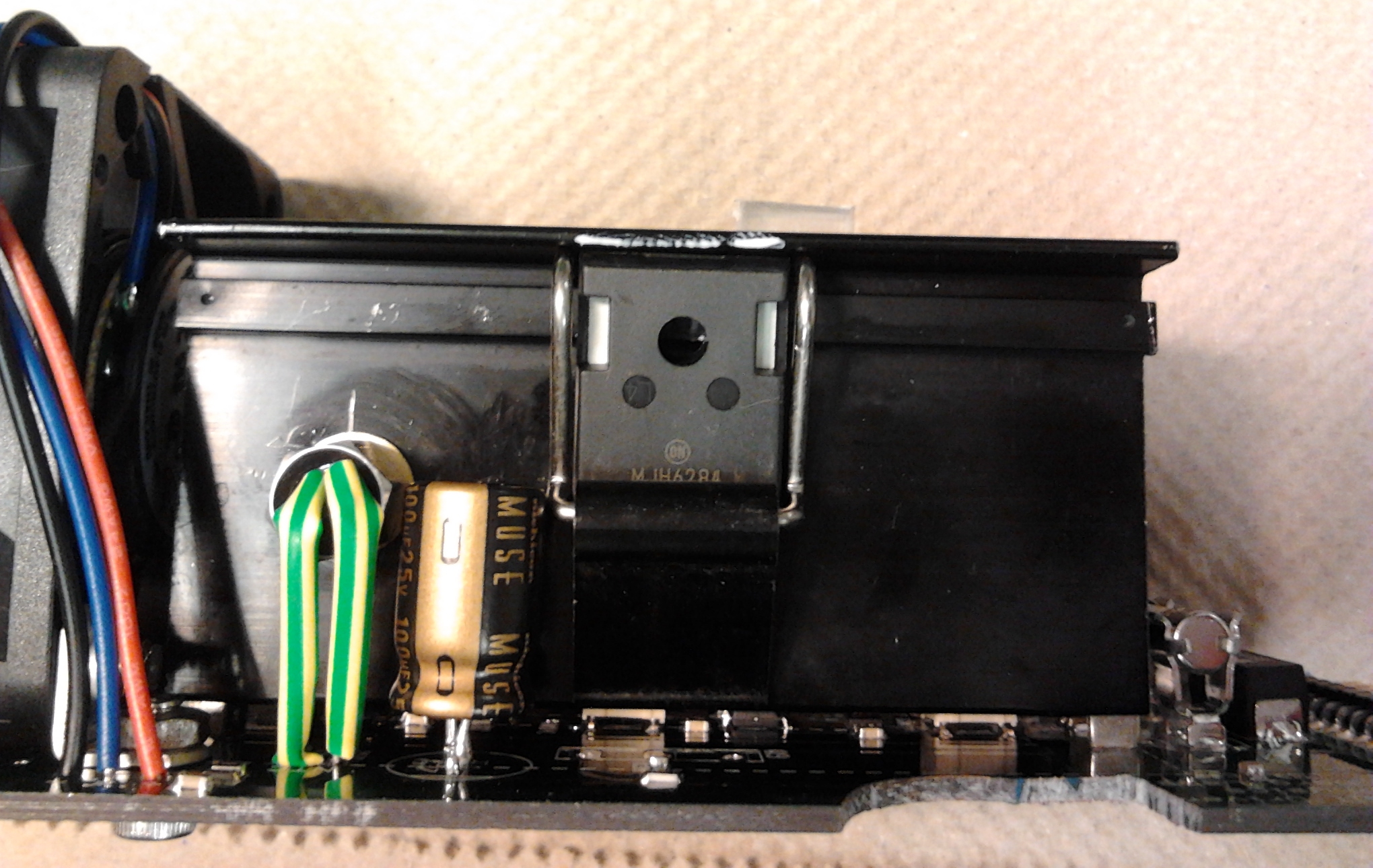
Step 1: Cut the leads on the old BJT, remove the BJT, unsolder the lead stubs, clear the
holes. (No picture available, never blown a BJT - yet.)
|
Step 2: Cut BJT leads to 30mm overall, put on thin coat of silicone thermal compound.
|
Step 3: Line up BJT with holes in PCB, slide leads under clip.
|
Step 4: Push BJT under clip.
|
Step 5: Slide BJT into place and flip up clip cam, then solder leads.
|
Return to homepage
| Sorry, no more chance for asking direct questions, queries, broken links, problems, flak, slings, arrows, kudos, criticism, comments, brickbats, corrections or suggestions. |
|

|