
|
 Alan Stummer
Research Lab Technologist |
|

|
DDS Comb |

|
Downloads
|
I am curious who uses what. Are these webpages a waste of time, or are they any help to others? Are the circuits, software and utilities appearing in other labs? Please send your comments or suggestions or what you have used (or not) or schematics of your version or pictures or anything! Email me, or be creative and send a postcard! I want to hear from the vacuum! |
Links
|
|
NOTICE: This webpage and associated files are provided for reference only. This is not a kit site! It is a collection of my work here at the University of Toronto in the Physics department. If you are considering using any schematics, designs, or anything else from here then be warned that you had better know something of what you are about to do. No design is guaranteed in any way, including workable schematic, board layout, HDL code, embedded software, user software, component selection, documentation, webpages, or anything. All that said, if it says here it works then for me it worked. To make the project work may have involved undocumented additions, changes, deletions, tweaks, tunings, alterations, modifications, adjustments, waving of a wand while wearing a pointy black hat, appeals to electron deities and just plain doing whatever it takes to make the project work. |
||
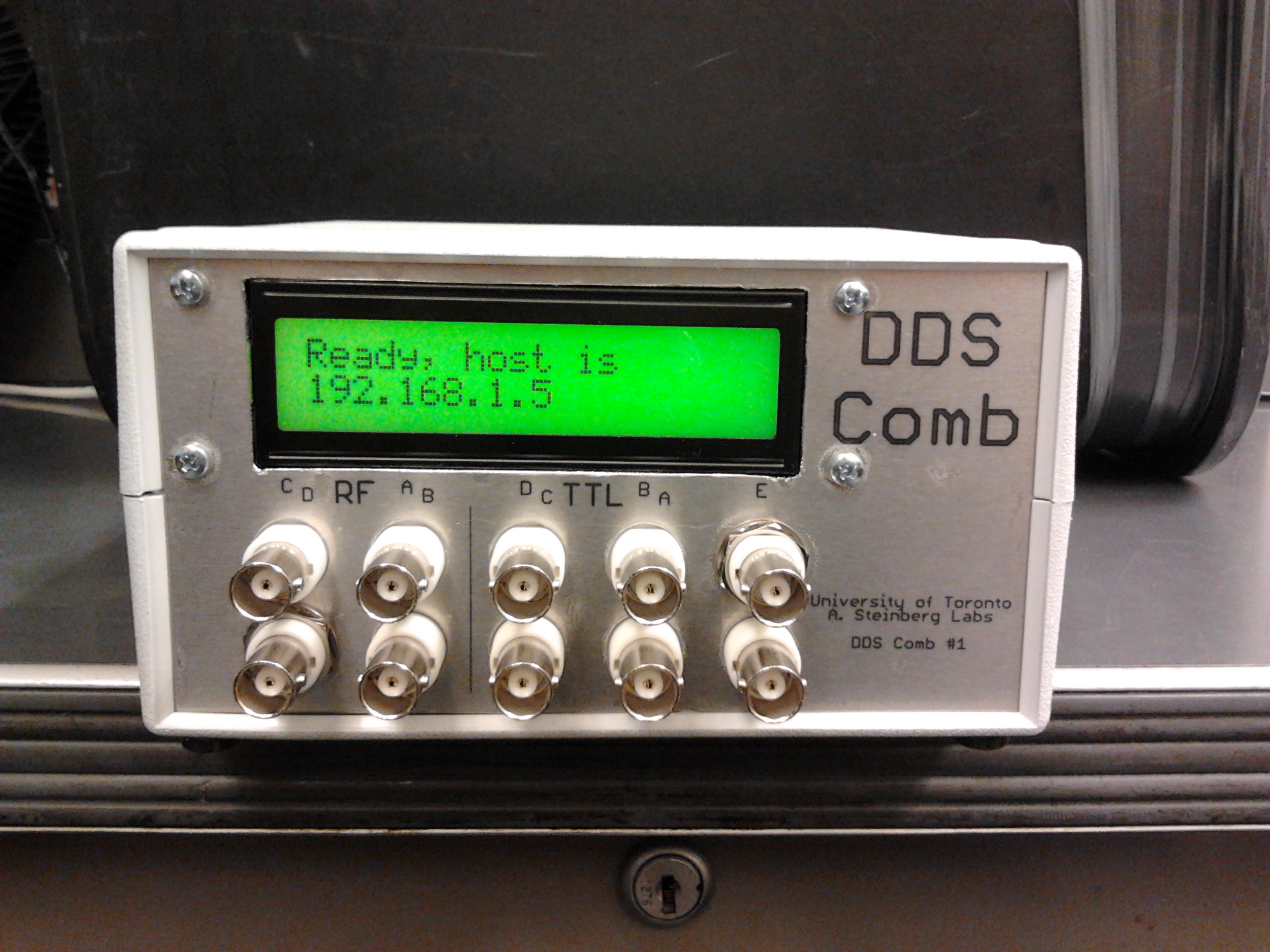
Started 2014 August for Greg Dmochowski in Aephraim's lab. The DDS Comb ("Comb") is similar to the General Purpose DDS except that there are up to four DDS channels. It's purpose is to generate up to four independent RF signals in the range of roughly 10MHz to 175MHz. The Nyquist frequency is 250MHz, hence the 175MHz upper limit. All four channels use the same clock so the frequencies will be locked to each other. The term Comb is used as it can generate four simultaneous independent frequencies.
The RF is generated by an AD9959 DDS for four channels (A to D). Alternatively, the AD9958 dual DDS can be used and only two channels (C and D) stuffed.
The DDS Comb requires a host computer to control it. They are connected over Ethernet (10/100BaseT, IP-v4, DHCP, TCP/UDP). The host runs either the test GUI (windows only) or a custom interface made by the user. The host sends commands to the unit, for example "Set Ch-A to 100.000001MHz" or "Set Ch-B to sweep between 50MHz and 60MHz in 1mS" or "Set Ch-C to toggle between 50MHz and 50.123456MHz" or "Advance Ch-D phase by 12°" or "Set Ch-A amplitude to 47%". As just implied, there are five TTL inputs which are assigned as amplitude ramps or frequency sweep directions. Details of the protocol between the host and the unit are here.
The Test GUI: Turn on the unit and ensure that it is plugged into the Ethernet. The display will show when it has an IP address from the DHCP. The GUI will show its name and IP address. Double click the name and once they host connects to the unit, the name should turn white. Check "Always this unit" to automatically connect to this unit when it sees it available. For reference, the GUI and unit's firmware version codes will appear.
All four channels are independent and almost identical. Each channel can output a fixed frequency or sweep a range of frequencies. To output a fixed frequency, Check the channel's fixed frequency radio button then enter the frequency in MHz, enter the relative amplitude in percent and the phase in degrees (see below for details on phase).
Frequency sweep is controlled by the channel's TTL input. When the input is high (>2V), the frequency sweeps up. When the input is low (<0.8V), the frequency sweep down. The frequency will sweep up as long as the input is high and the frequency has not reached the high frequency. Conversely,the frequency sweeps down as long as the input is low and the frequency has not reached the low frequency. To sweep a frequency range, first select the channel's frequency sweep radio button. Set the upper and lower frequency limits. Note that the upper frequency must be higher than the lower frequency. The frequency sweep slope is set by two parameters: step size (in MHz) and step time (in nS). Every step time interval, the frequency shifts by the step size. The product of the two can be read as MHz/Sec or MHz/uS. Note that the time step is truncated to the integer multiple of 8nS, e.g. 22nS will actually be 16nS. Selection of these two parameters depends on the application. If frequency accuracy is desired, use a small frequency step and a larger time step. Conversely if an accurate sweep time is desired then use a small step time and a larger frequency step. Note that the frequency will never under- or over-shoot the range. For example if stepping from 1MHz to 1.5MHz in [very coarse] 0.15MHz steps then the frequency steps will be 1MHz, 1.15MHz, 1.3MHz, 1.45MHz, 1.5MHz when sweeping up, then 1.35MHz, 1.2MHz, 1.05MHz, 1MHz.
When a channel if in fixed frequency mode, its TTL input can be used to ramp up and down the amplitude. When ramping is selected, a high input will ramp up the output from zero to the set amplitude, a low input will ramp the output back down to zero. The amplitude ramp can be done in 1uS up to 255uS. The reason for a finite ramp time is to limit the spectrum.
Only CH-A can be amplitude ramped when frequency sweeping. While the CH-A TTL input will control the frequency sweep direction, TTL-E will control the CH-A amplitude ramping. Note that where TTL-A to -D ramp up with a high input, TTL-E is reversed so that a high input will kill CH-A.
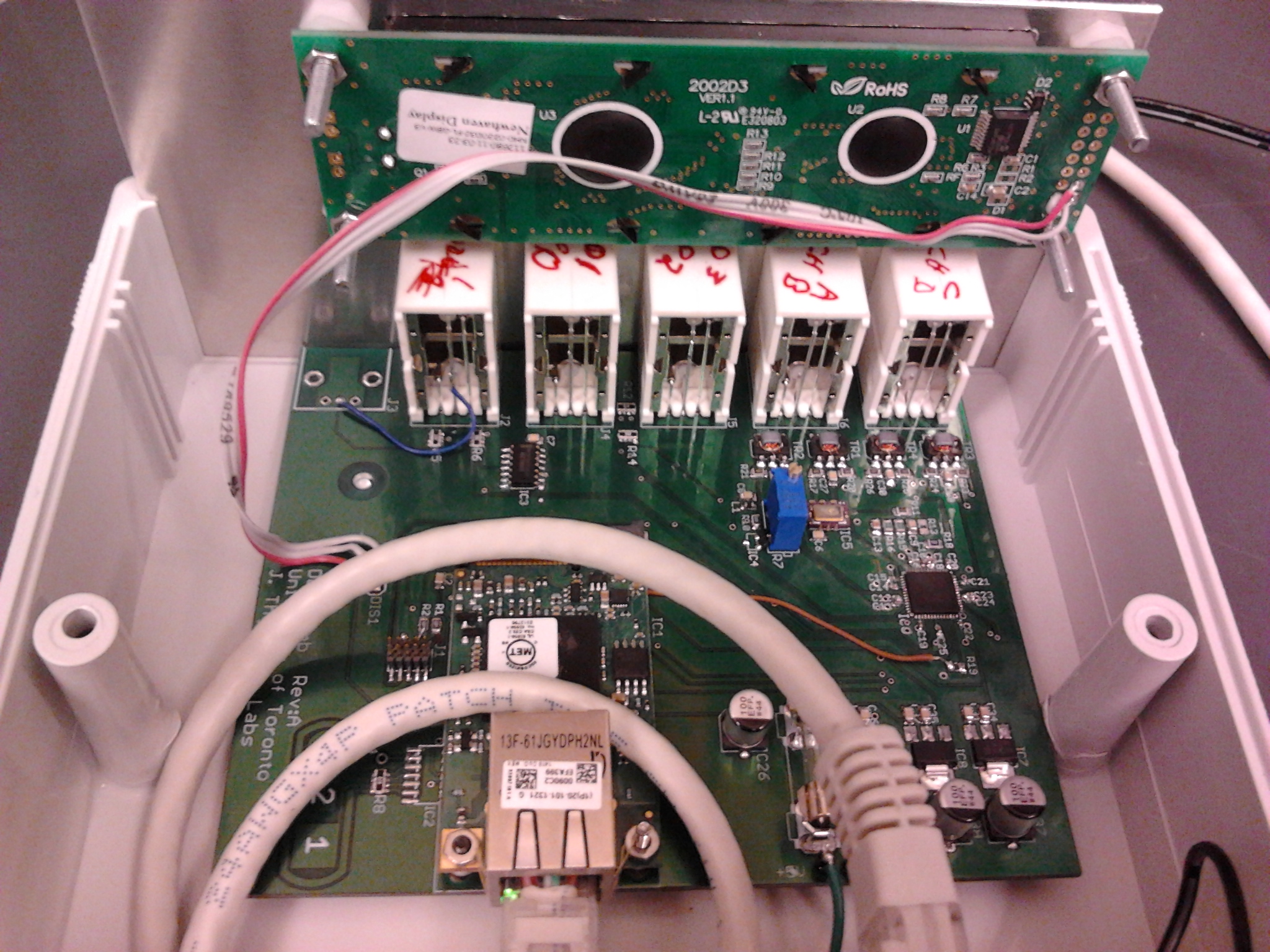
Calibration is simple. Set a frequency on any channel, say 10MHz or 100MHz. Monitor the output frequency. Inside the unit is a single trimpot. Turn to calibrate.
Each channel's phase is relative to itself, not a global reference. Think of the output frequency as a rotating phase (which it is anyway) and that the phase adjustment only adds an offset to that. For example, if both CH-A and CH-B are set to 10MHz they will probably not be in phase but will be phase locked. If CH_B is then set to 11MHz and back to 10MHz then their relative phase will be pseudo random (dependant on the time at 11MHz). Repeating this 10-11-10MHz stepping will always give different phases between CH-A and CH-B. Hitting the "Sync Phases" button will return all channels to a global phase reference, putting CH-A and CH-B back in the same phase. However, any phase offsets will still apply giving the appearance of not being phase locked.
| Parameter | Min | Max | Description |
| Frequency range
|
30KHz | 175MHz | Adjustable in 1Hz steps, limited by transformers and Nyquist
|
| Amplitude range
|
0mW | -6dBm | Adjustable in 1% steps
|
| Phase range
|
0° | 359° | Adjustable in 1° steps. See phase description for details |
| Amplitude ramp range
|
1uS | 255uS | Adjustable in 1uS steps |
| Sweep step size | 1Hz | 175MHz | Adjustable in 1Hz steps |
| Sweep step time | 8nS | 2.047uS | Adjustable in 1nS steps but rounded to integer of 8nS steps |
| Command processing time | 90uS | 460uS | Exclusive of Ethernet/Internet packet delivery time.
These times may be shortened but will require more development time. |
Due to a quirk of the AD9958/9 DDS, an unexpected effect may occur. These specific conditions must apply: 1) CH-A is frequency sweeping, 2) CH-A is amplitude ramping, 3) the TTL-E is high, 4) a command is sent to the unit. If these four conditions exist then the amplitude will ramp down while any command is being processed. This does not apply to heartbeats between the host and unit. Neither does it apply if setting the fixed frequency of any channel that is sweeping. However, it does apply if setting the fixed frequency of any other channel in fixed frequency mode. This interruption can last from 90uS to as long as 460uS. It is not possible to bypass this effect unless the TTL-E input is low, in which case turning off CH-A amplitude ramping will cause the output to step to the set amplitude.
Return to homepage
| Sorry, no more chance for asking direct questions, queries, broken links, problems, flak, slings, arrows, kudos, criticism, comments, brickbats, corrections or suggestions. |

|

