![]()
![]()
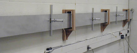
The waveguide is an aluminum channel, about 5 cm wide and 15 cm high, approximatelyl 6 m long. Microphone are located at the 1/4, 1/2 and 3/4 marks marks, which can be slid up and down the height of the waveguide, and pushed in and out to sample almost every point in the cross-section.
The waveguide is mounted elastically, to isolate it from noise trasmitted in the structure of the building.
At the far end, in the picture at right, there are three speakers mounted in a row up the height of the waveguide, which can be driven with different amplitudes.
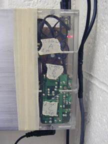
Three 5 cm speakers with small amplifier-boards are housed in a plexiglas box, with 3.5mm stereo jacks for their connection. The speakers are driven by a National Instruments DAQ card in the computer, which includes a digital-to-analog converter. With this, a LabVIEW program on the computer drives two output lines with arbitrary waveforms. The software provided will let you control the frequency of sound applied, and the duration of sound-pulses, from continuous to pulses of a fraction of a cycle. The interface between the patch-panel for the computer card and the speakers is a small blue box with binder terminal posts which can accept banana plugs or wires.
Technical Note: Two adjacent speakers of these share a ground connection, and the third is indepedent, so a single signal can be connected with reversed leads to drive the two outside/end speakers 180° out of phase.but with the same amplitude, and the centre speaker can be driven independently. Or two arbitrary drive signals can go to the end speakers, with the centre one grounded to 0V signal.
It's also possible to modify the drive software slightly to permit three independent waveforms for the three speakers, but this actually cuts the maximum rate of signal generation in half; and it's not necessary, in order to generate the normal modes needed for the basic experiments.
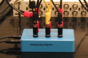
This box has three pairs of binder terminal posts which connect to the drive-speakers, a pair for each speaker. A BNC-to-banana plug cable then connects two outputs of the digital-to-analog card to the speakers. Banana-to-banana plugs let you connect the third speaker to be grounded (no signal), or in phase with, or out of phase with one of the other speakers.
Technical Note: Two adjacent speakers of these share a ground connection, and the third is indepedent, so a single signal can be connected with reversed leads to drive the two outside/end speakers 180° out of phase.but with the same amplitude, and the centre speaker can be driven independently. Or two arbitrary drive signals can go to the end speakers, with the centre one grounded to 0V signal.
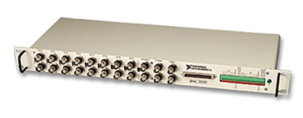
This patch panel facilitates connections to the multifunction digital acquisition card (NI MIO-16) installed in the computer. It presents BNC connectors for outputs from the digital-to-analog converters, and for inputs to the analog-to-digital converters, as well as connectors for other timing and digital input/output functions.
We use DAC0Out and DAC1OUT (analog output) to drive the speakers, and sometimes ACH0 through ACH7 (analog input) to record signals from microphones.
Manual for BNC-2090
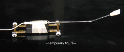
This is a microphone on wheels which can be inserted into the waveguide. It has a long fine cable attached, which can reach the length of the waveguide. The microphone is positioned using a metal spooled tape-measure, which is rigid enough to push and pull the microphone to different positions while providing at the same time a measure of the position down the waveguide. The tape measure end attaches to strong magnets on the Rover1 (be careful of your credit cards near those magnets).
This is a microphone array on wheels which can be inserted into the waveguide. It has a long fine cable attached, which can reach the length of the waveguide. The microphone array is positioned using a metal spooled tape-measure, which is rigid enough to push and pull the microphone to different positions while providing at the same time a measure of the position down the waveguide. The tape measure end attaches to strong magnets on the Rover (be careful of your credit cards near those magnets).
The eight microphones of the array feed into eight input channels of the BNC-2090 patch panel; their signals are digitized by the multifunction data acquisiiton card of the computer, and displayed using special LabVIEW software, which makes a profile of the pressure variations along the array, and then shows the evolution of this profile, of the wave within the waveguide.

![]()
Last revised: 13 April 2003 -- rsm