Alan Stummer, Research Lab Technologist
Planar Triode Grid
Pulse (A.K.A. n-Pulse Selector)
Downloads
- Return to the newer version, the fast FET base n-Pulse Selector.
- View list of all files
Overview
For Robin Marjoribank's lab. This is the old and now abandoned attempt at the n-Pulse Selector. The fast FET based version is here.
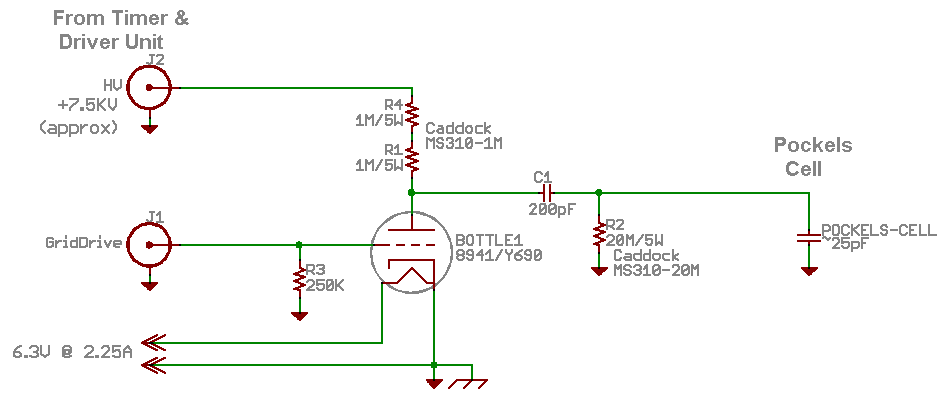
A pockels cell unit is used to gate a pulse train on during the clean pulses, AKA the n-Pulse Selector because it gates a preset number of laser pulses. The present unit is made by Medox, model DR85-A-AA2. The unit is in two parts. The model DR85 driver is located slightly away from the optical table, containing the timing circuits, HV supply and triode grid driver. It is connected to the model 700/800 pockels cell assembly with cables, this latter unit containing the pockels cell, a 8941/Y690 planar triode and associated minor circuitry.In operation, the driver is signaled at the start of the pulse train. After a preset delay, it sends a short (~10nS) pulse to the planar triode grid to turn it on. While the triode is on, the anode is around 0V. C1, which was charged to HV during the idle time, bootstraps the cell to a large negative voltage (about HV / 2) and loses half its charge via R4. At the end of the grid pulse, the triode turns off and C1 and the cell hold their voltage reasonably well.
The pockels cell effective attenuation in any polarization is sinusoidal against voltage - e.g. if at 0V it is said to be 0% transmissive, and at 6KV it is also 0%, then at 3.5KV it is 100% transmissive (excluding losses). To setup the Medox DR85, 1) adjust the cell with zero bias to full attenuation, 2) at the end of the experiment, adjust the HV for full attenuation, 3) during the 10uS experiment window, adjust the grid drive and/or R4 for full transmission.
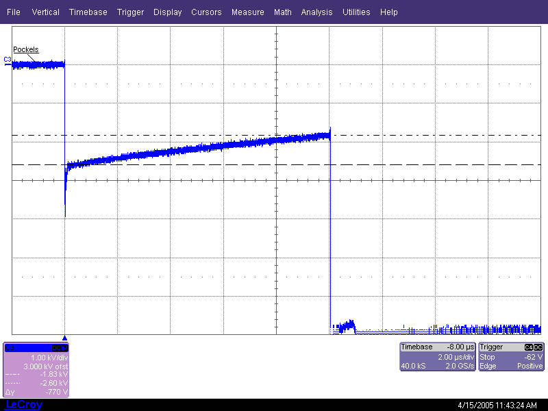
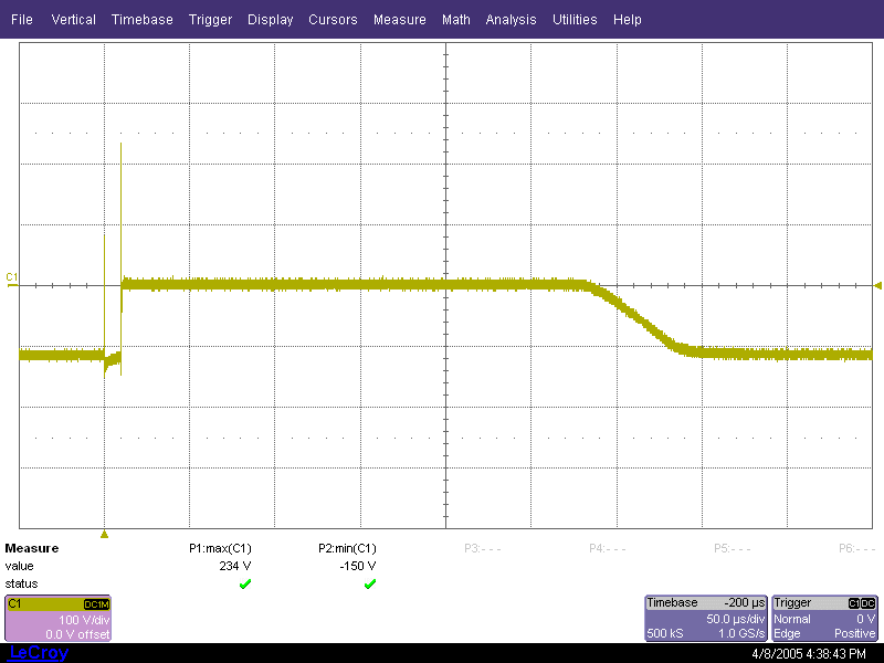
The problem with the whole assembly is that the grid drive is sloppy and rings, causing modulation on the leading edges of the pulse train and a gradual decrease in the envelope shape. This project cleans up the cell voltages while using as much of the existing controller units as possible.

Fig 1. Pockels cell assembly's existing circuit (best guess)

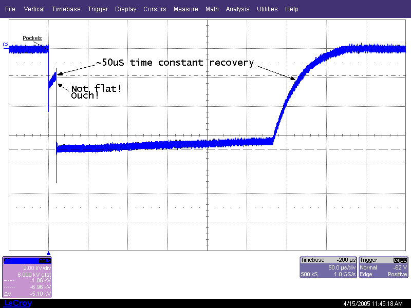
Fig. 2. Overview of cell when driven by DR85. Note nasty slope during 10uS experiment window.

Fig. 3. Cell during 10uS experiment window when driven by DR85.

Fig. 4. Overview of grid drive from DR85 driver.
Return to homepage Please report broken links, problems, corrections and suggestions to astummer_at_physics.utoronto.ca.