
TOP Coil Quadrature Driver
|
Downloads
Overview Drivers Digital Signal Generation Capacitors and Transformers Lessons Learned |
|
NOTICE: This webpage and associated files is provided for reference only. This is not a kit site! It is a collection of my work here at the University of Toronto in the Physics department. If you are considering using any schematics, designs, or anything else from here then be warned that you had better know something of what you are about to do. No design is guaranteed in any way, including workable schematic, board layout, HDL code, embedded software, user software, component selection, documentation, webpages, or anything. All that said, if it says here it works then for me it worked. To make the project work may have involved undocumented additions, changes, deletions, tweaks, tunings, alterations, modifications, adjustments, waving of a wand while wearing a pointy black hat, appeals to electron deities and just plain doing whatever it takes to make the project work. |
|

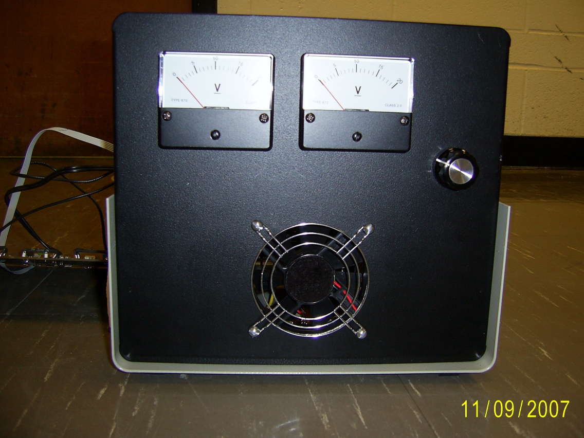
The TOP coil driver module runs the coils in constant voltage (CV) mode. Although constant current (CC) is preferred, time was not available to develop stable current feedback controls. An external device monitors the field, send the data to the controlling computer, which adjusts the CV drive level.
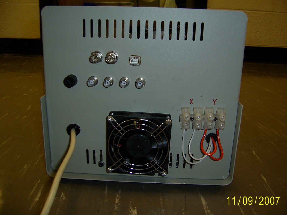
The TOP coil driver module has two outputs and three inputs. The outputs are obvious: current for the X-axis and Y-axis coils. The inputs are 1) a TTL level "Disable" to externally turn off the coils, 2) a TTL level "Trigger" to start the amplitude profile or to step to the next part of the amplitude profile, and 3) a USB input. The USB writes to the module. It can reset the module, define the phase angle between X-axis and Y-axis or load the amplitude profiles to be executed.
At 9.766KHz, the coil inductance swamps the coil resistance, making it appear almost totally inductive. To push 20Ap through the calculated impedance of 4.60 Ohms takes 92Vp. Rather than use 20Ap drivers, a toroidal transformer per pair is used to allow a higher voltage and lower current driver. The primary is run from a ±24V supply. The coil pair is in series resonance with a ~4µF capacitor (made from parallel low loss capacitors), the LC driven by the transformer secondary also in series. The transformer now only has to make up the losses, mostly the coils', capacitors' and other parasitic resistances.
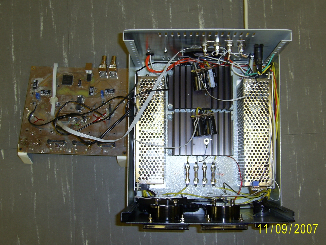
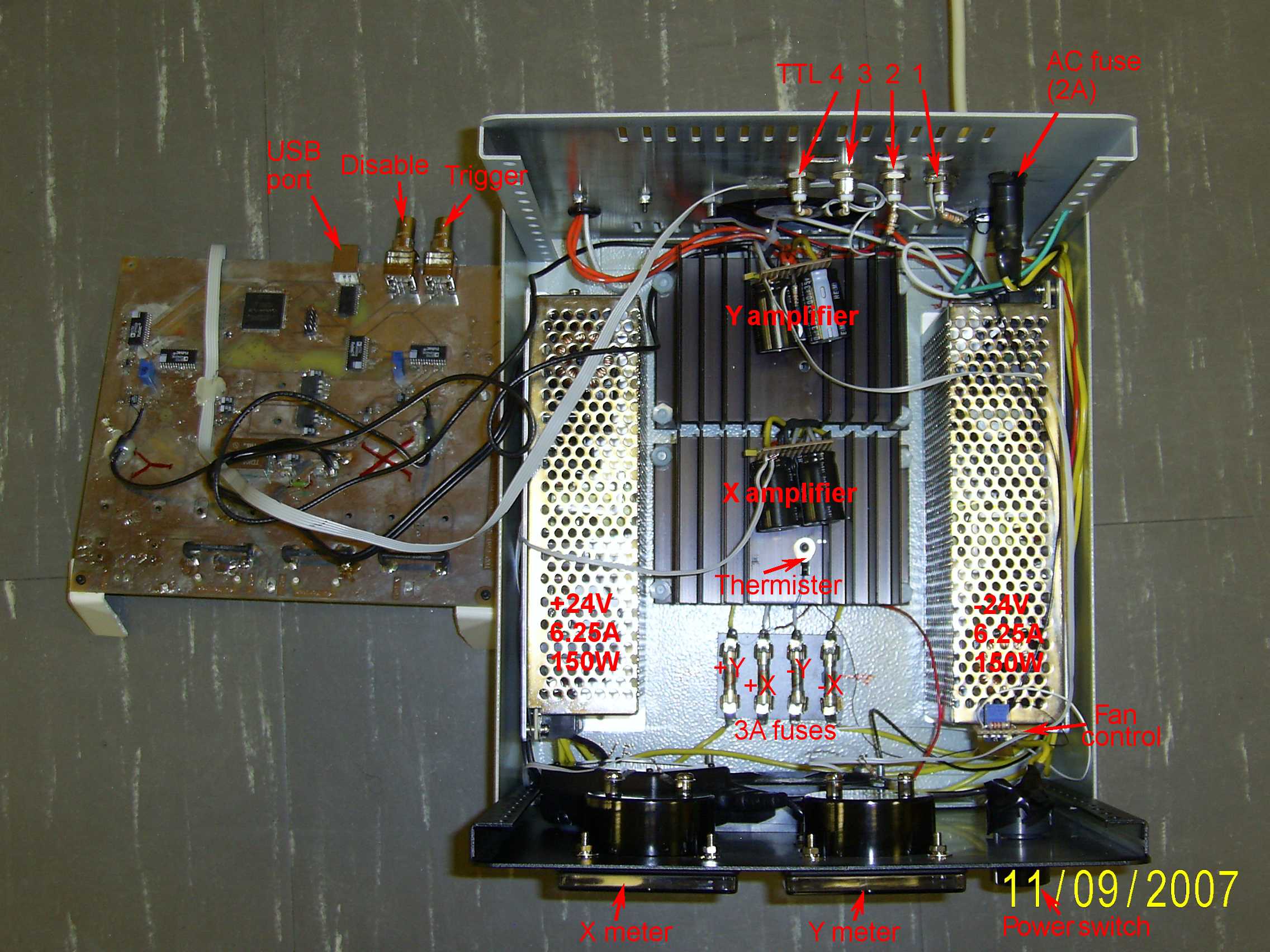
Two driver methods were simulated and tested. Accurate simulations cannot be made for the LC and transformer resonance so final details were empirical. In the first method, output FETs are run in complimentary common-source class AB or B. Bias currents are kept low (class AB1) so that any drifts and temperature sensitivities in the FETs will not greatly increase the bias current. A high speed opamp driver corrects crossover distortion. The FETs are mounted on two heatsinks, one for the two N-FETs and one for the two P-FETs. Two temperature controlled fans cool the heatsinks. This method was limited by the C dg ("Miller") capacitance feeding back into the opamp, creating a pole and causing it to be unstable and oscillate. An isolation resistance between opamp output and the gate biasing network reduced the size of the pole but also reduced the loop gain. Tuning the network would have been possible but complex and too empirical.The second method tested was using a high power opamp, actually an audio amplifier. The LM3886TF can output ±11.5A from up to ±46V with a GBW product of 3MHz. It proved to be worthy of the task. Even at a gain of 40 and a resultant bandwidth of 75KHz, no distortion was visible on its output, let alone the high-Q resonant coil current. Heatsinking at 1°/W is adequate. Power would ideally be ±40-45V to minimize saturation losses but ±24V because of available supplies. Preliminary tests at coil current of 20Ap with mediocre resonant capacitors (tan-d = 1% at 10KHz) showed power draw of about 150W, but this cracked a capacitor and melted the tape holding the test coil in 15 seconds. Final tests - with the coils immersed in cooling water and polypropylene capacitors - drew 50W per channel.
To supply the high currents, the coils are in series resonance with capacitors and the transformer secondary. The capacitors have to carry 14Arms, a low DF (Dissipation Factor) is required and of course be non-polarized. Only polymer film dielectrics would work. Polypropylene dielectrics such as AVX's FPX86N305J are exactly as required, trimmed by a few extra lower value caps in parallel such as Epcos' B32621A4473J polypropylene caps. With an LC resonant Q-factor of about 30, adjusting the capacitance is critical. By monitoring the transformer voltage and current, resonance is reached when the two are in phase, with the current falling off by the COS() of the angle.
Also problematic was the transformer. Toroids from CWS ByteMark Inc. were used. Thumbing our noses at critical design, we used the largest core available, an F-290-43: 2.9" diameter, material #43 with a relative permeability of 850. The primary is 27 turns of 20AWG wire. The secondary is 8 turns of 16AWG. Due to the finite permeability, the toroid must be kept clear (>25cm) of magnetic materials.
An Altera Cyclone II FPGA both interfaces to the host computer and generates the two signals and amplitude controls. The FPGA is a TQFP package so it can be hand soldered, BGAs suck.. The firmware is written in Verilog with System Verilog extensions, using Altera's Quartus II. The sine wave is held in a 1024 x 12-bit lookup table (LUT). The LUT is stepped through completely at 9.766KHz (80MHz clock ÷ 4 ÷ 1024) and sent to a signed DAC. The DAC's outputs are converted to a fixed amplitude sine wave by an opamp. A second DAC and opamp generate a static but controllable gain control voltage. The sine wave is sent to a variable gain amplifier (VGA), the gain of which is logarithmically controlled by the gain control voltage. This resulting variable amplitude sine wave is sent to the LM3886TF power amplifier, an external toroidal transformer and finally the resonant capacitors and the MOT coil pair. This whole process is repeated for the second (Y-axis) channel, except that the relative phase of the generated sine wave is set by the USB commands, but typically 90°.
Amplitude records (text file) are held in the FPGA. The records are loaded into the FPGA via the USB then executed starting with an external Trigger pulse. The records define what the amplitude [of the voltage] should be in the X-axis and/or Y-axis coils. The amplitude can remain stable or linearly ramp up or down at a defined rate. Non-linear ramps, such as a logarithmic, exponential or arbitrary shapes must be made up as a series of linear segments. Up to 1,000 records can be used.
The USB can only transfer one byte at a time so several USB transfers are required to load one record. Once all bytes are sent and that record is complete, the next byte will start the next record. The USB just bangs away at the records until all records are loaded, then does nothing. The first external Trigger pulse starts the records executing. After the last record is executed, the coils stay as is, as the end of the last record left them. If the next activity is an external Disable input then they turn off. If the next activity is an external Trigger pulse then the execution of the records starts over again from the beginning. If the next activity is from the USB then what is requested by the USB is done.| Sorry, no more chance for asking direct questions, queries, broken links, problems, flak, slings, arrows, kudos, criticism, comments, brickbats, corrections or suggestions. |
|

|