

|
 Alan Stummer
Research Lab Technologist |

Tapered Amplifier
|
Downloads
|
|
Overview
Modifications to the LDTC2/2 (2006) Modifications to the LTDC1020 (2014) How to Set Up |
|
NOTICE: This webpage and associated files is provided for reference only. This is not a kit site! It is a collection of my work here at the University of Toronto in the Physics department. If you are considering using any schematics, designs, or anything else from here then be warned that you had better know something of what you are about to do. No design is guaranteed in any way, including workable schematic, board layout, HDL code, embedded software, user software, component selection, documentation, webpages, or anything. All that said, if it says here it works then for me it worked. To make the project work may have involved undocumented additions, changes, deletions, tweaks, tunings, alterations, modifications, adjustments, waving of a wand while wearing a pointy black hat, appeals to electron deities and just plain doing whatever it takes to make the project work. |
||
Overview
2006 version for Matt Partlow in Aephraim's lab, started April 2006. The Tapered Amplifier is an optical amp providing up to 1W at 780nm with a fairly low gain of 13dB (that's 20 in English). It is used in the BEC experiments.
2014 version for Aephraim's lab too, similar but uses an updated module.
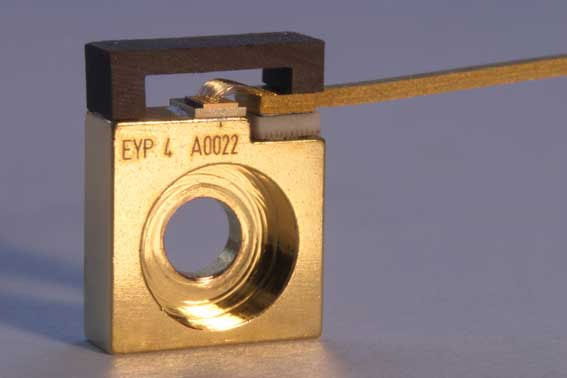
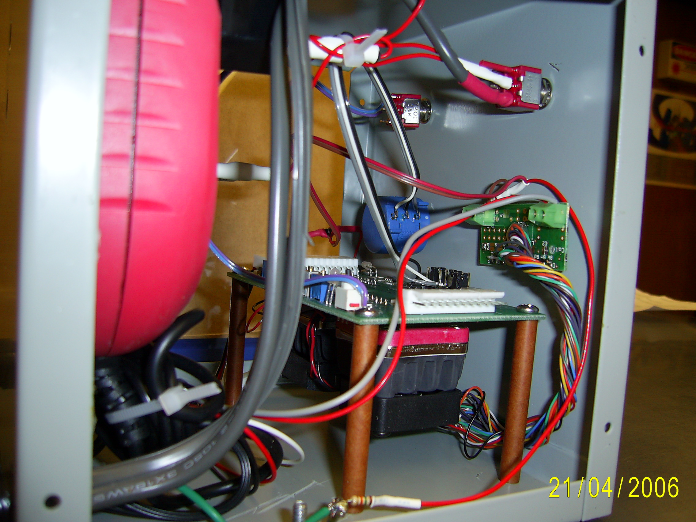
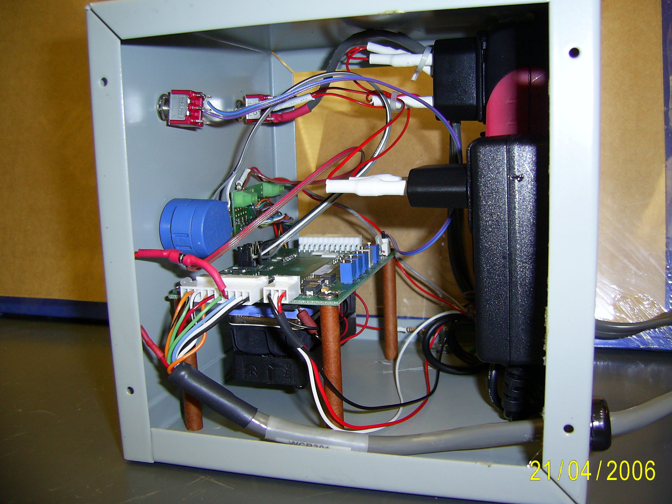
The tapered amplifier is an assembly based around the Eagleyard Photonics model EYP-TPA-0780-1000 (or file directly from Eagleyard) GaAs device. The original unit was from 2006 using the LTDC2/2 unit, the second unit was made in 2014 with the newer LDTC1020 unit.
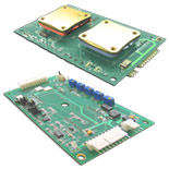
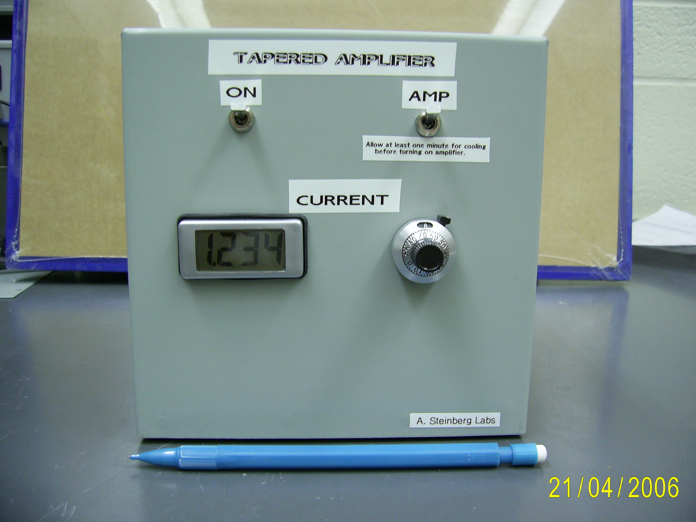
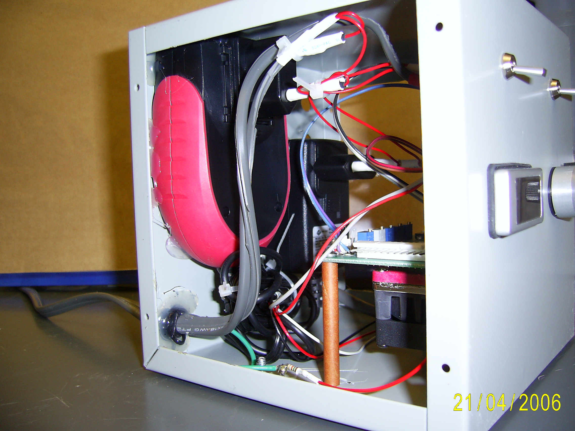
The tapered amp is driven up to 2.0A only in CC (Constant Current) mode, with a 2.5A TEC (ThermoElectric Cooler) to maintain temperature. From Wavelength Electronics , the LDTC2/2 module (2006 version) or the LTDC1020 (2014 version) combines a laser driver module and a TEC controller module on one PCB. The full blown version was used, which includes two heatsinks and fans plus all cables and mounts. A ten-turn pot sets the current, subject to the LDTC2/2 set current limit. A Martel model QM-140V panel voltmeter is set to display the current.
Modifications to the LDTC1020 and Meter (2014)
- Use the 2014 wiring diagram.
- Set the three slide switches : TREF to Int (down), CC/CP to CC (down), LDREF to Ext (up).
- Set the little laser enable switch to Enable (up).
- On the meter connection board, add 10uF from V+ (red) to Com (brn).
Modifications to the LDTC2/2 and Meter (circa 2006)
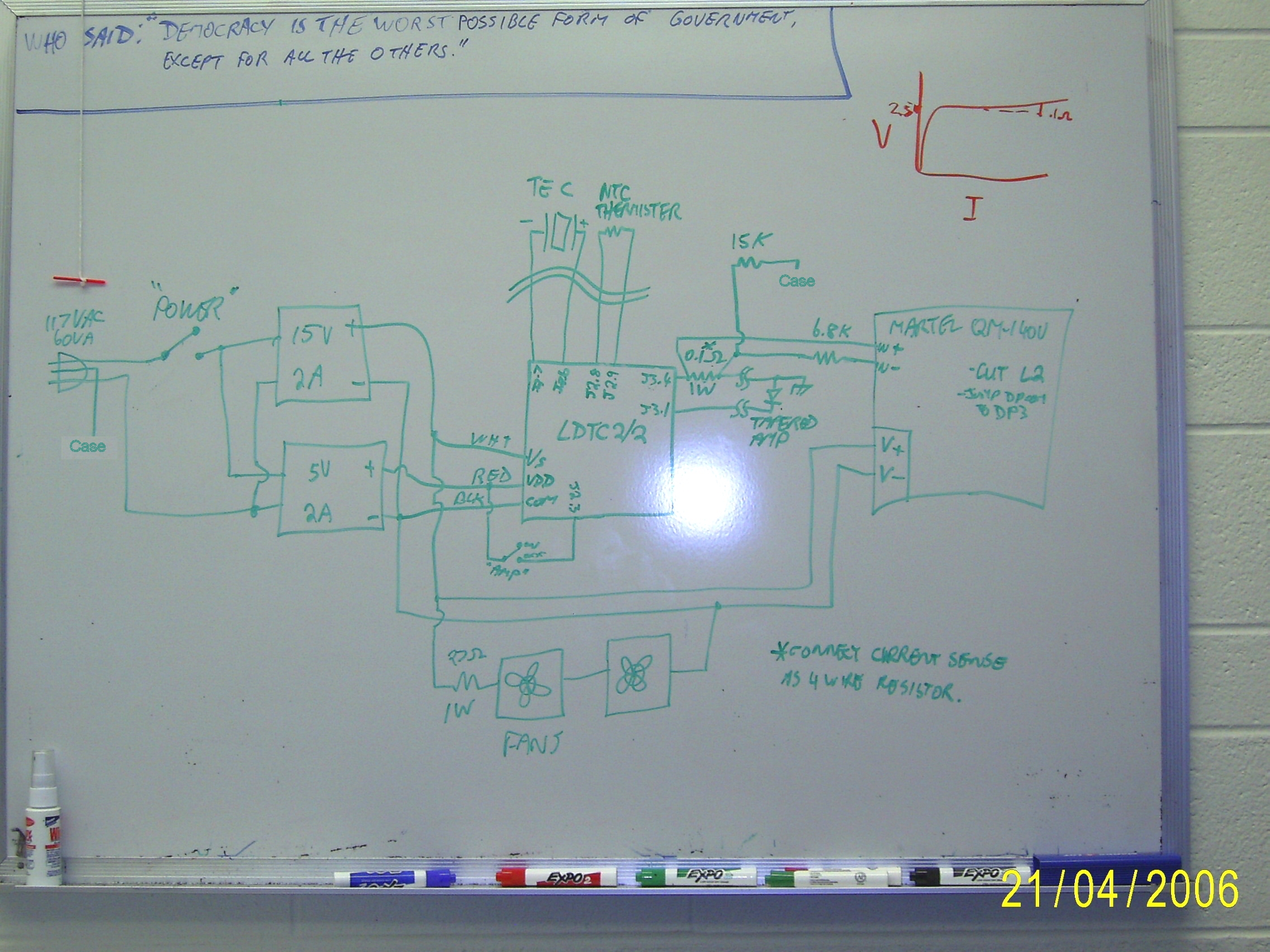
- Use the 2006 wiring diagram.
- Set switch S2 to "CC" (Constant Current).
- Set unnamed switch (laser on) to "On".
- Set jumper JP1 to 1-2 position (set temperature by R2 Tset).
- Set JP2 to 1-2 (set current from Ext Vset).
- Set JP3 to anything, don't care (CP photodiode sense resistor value).
- The two Rsense R14-15 resistors are factory set to 2.2A max. For lower ranges, change according to the LDTC2-2 data sheet , page 11.
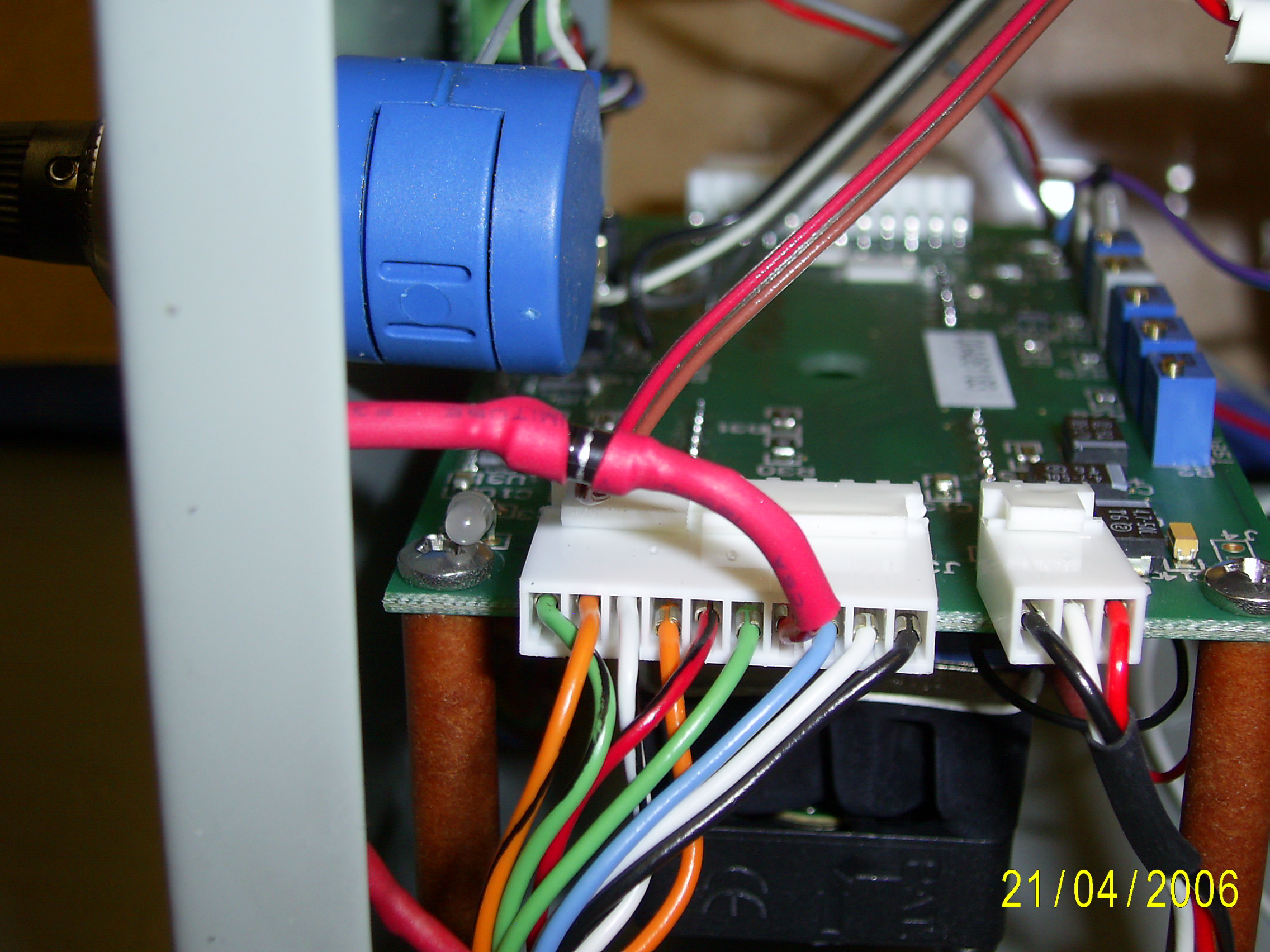
- Connect front panel 5K laser current pot CW and CCW across R6 (Iset).
- Connect front panel pot wiper either direct to J2-5 (Ext Vset) or directly to R8, or via a switch to select between this pot and a BNC for remote control. Note that the input bias current causes an offset of several hundred mA. When using an external setpoint via a BNC as above, a slight negative voltage may be required to reach zero current.
- Connect the meter wires to the meter board. On the board, cut link L2 and jumper DP3 (decimal point 3) with solder.
- Instead of using J2, solder the front panel laser shutoff switch directly to R16 on the LDTC2/2.
Refer to Wavelength Electronics' LDTC1020 instructions ot the LDTC2-2 instructions for details. There are two independant sections: temperature control and current control.
- With an external thermister or temperature probe, monitor the block temperature. Put an ammeter in series with the TEC. Turn on the unit. Turn the Tset trimpot (temperature setpoint) so that the unit is cooling. Adjust LimA (TEC cooling current limit, CW to reduce) for 1A or whatever the cooling current limit should be. Blowing a fan on the tapered amp will increase the thermal loading and run the TEC into cooling current limit permanently.
- Similar to the above step, set the temperature setpoint high with Tset and adjust LimB (TEC heating current limit), about 0.33A or whatever you prefer. Not that since the tapered amp is run below ambient and with a heat source (the tapered amp), it will always run in cooling mode anyway.
- Reset the Tset trimpot to the desired temperature. Test for proper operation and stability.
- For safety of the tapered amp, replace the tapered amp with two diodes in series capable of carrying 2A, with an ammeter in series. Turn on the amp switch, set to maximum. Adjust the Ilim (laser current limit) for 2A or whatever your limit is. Remove the diodes, connect the tapered amp.
- Finished! Note that the Iset trimpot (tapered amp current setpoint) is disconnected and replaced by the front panel pot.
Return to homepage
| Sorry, no more chance for asking direct questions, queries, broken links, problems, flak, slings, arrows, kudos, criticism, comments, brickbats, corrections or suggestions. |
|

|