University of Toronto, Physics, Quantum Optics
Alan Stummer, Research Lab Technologist

E2V CCD Assembly


Downloads
Overview
Warnings
Connections
TEC
Pressure Measurement With A Thermistor

Downloads
  • All files in the project.
  • A short video of it working (wmv format, 8MB)
  • Timing of Req For Int input and Grab output relationship
  • Timing of   Video O/P, Line Blank and Pixel Clock outputs relationships


  • Overview

    The CDR01-1 CCD Assembly from E2V (formerly EEV or English Electric Valve Co., and I would change it too) is reworked to make it functional.  It rasion d'etre is as an x-ray spectrometer.  Imaging is 2 axis with analog intensity output.  It is based around a TEC cooled Marconi CCD15-11 CCD.

    E2V CCD Driver Format with Marconi CCD15-11 or CCD30-11
    Frame format:  proprietary, non-interlaced.
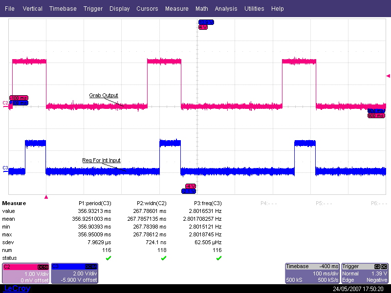
    Frame rate:  Line rate / 256 lines = 3.73Hz => 268mS
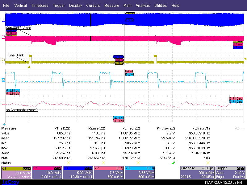
    Line rate:  956.00Hz (AKA "Line Blank" connector on back)
    Sample rate:  1.000MHz (AKA "Pixel clock" connector on back, sample on either edge)
    Pixels:  256 x 1024 (plus 8 blank at either line end, for apparent size of 256 x 1040)


    Warnings
    1. The CCD integration time and sample period is set externally by a signal generator.  Signal levels are TTL: 0V < Low < +0.7V, 2.0V < High < 3.5V.   Never go below zero or above +5V, absolute maximums.
    2. If the signal generator is on and running when the control unit is off, the latter may be damaged.   Always turn on the control unit before turning on and/or enabling the signal generator, and always turn off and/or disable the signal before turning off the control unit.
    3. Both the buffer box and the seperate camera box (not directly associated with this page but used in the same experiment) must have atmospheric pressure (approx 101.3Kp) to cool their electronics. Thermisters inside these units use self-heating and convection cooling to roughly measure air pressure.   Always test for pressure inside the units as described below .
    4. Be careful to connect the TEC with the proper polarity: red is +ve, white is -ve.   Reversed TEC connections will cook the CCD as the TEC burns out.

    Connections
    1. Plumb cooling water through the vacuum assembly head.
    2. Connect the TEC supply to the TEC.
    3. Connect the DB-37 between the control unit and the buffer box, through the vacuum connections.
    4. Connect the video output from the buffer box to the control unit (front SMA connector), through the vacuum connections.
    Connect the control unit to the DPI-IMAXX  frame grabber as follows:
    1. Connect a signal generator to control unit Req For Int, TTL levels, high is integration time, low must be greater than 268mS.
    2. Connect control unit Video O/P to frame grabber Red.
    3. Connect control unit Grab to frame grabber V Sync.
    4. Connect control unit Line Blank to frame grabber H Sync.
    5. Connect control unit Pixel Clock to frame grabber PCLK, terminate at grabber end with 50 or 75 Ohms.
    Configure MAXXGrab EEV as follows for the CCD15-11:
    FireWire camera connections (a Firewire camera is inside a small box at atmospheric pressure, DA-15 connectors through chamber, DB-9 connectors through camera box):
    All DA-15 and DB-9 connectors are connected pin for pin as follows.
    Pin 1:   Firewire pin 1 (wht)
    Pin 2:   Firewire pin 2 (blk)
    Pin 3:   Firewire pin 3 (pnk)
    Pin 4:   Firewire pin 4 (blu)
    Pin 5:   no connection
    Pin 6:   Firewire pin 5 (red)
    Pin 7:   Firewire pin 6 (grn)
    Pin 8:   Thermistor inside camera box, NTC 1K Ohm at 25°, one terminal
    Pin 9:   Thermistor inside camera box, NTC 1K Ohm at 25°, other terminal
    Pins 10-15: no connection


    TEC

    The TEC (Thermo-Electric Cooler) cools the CCD to approximately -40°.  The device is specified down to 235K.  It is Lairdtech model 2-CP-055-065-71-31, rated at Vmax = 8.6V, Imax = 4.3A, DeltaT @ max = 85º. Suggested operation is at 2.5A (should be 5V) for estimated DeltaT of 49º.  With summer cooling water estimated temperature of 20º, estimated TEC temperature is -30º.

    Pressure Measurement With A Thermistor

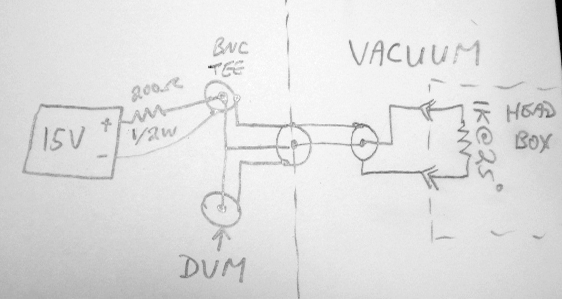
    Both the buffer box and the camera box require 1 bar pressure for cooling the electronics.  Loss of pressure could cause the circuits to overheat and fail.  A thermistor inside each of the two boxes roughly measures the pressure.

    The thermistor is in a voltage divider with +15V supply and 200 Ohm pullup.  The thermistor dissipates roughly 1/4W.  Air convection cools it, a vacuum allows it to heat up more.  With 1 bar ambient pressure, turn on the 15V/50mA supply, allow several minutes for the thermistor to stabilize, measure the voltage; it should be about 7.2V.  Pump down the chamber.  If the box looses pressure, the thermister will heat and the voltage drop to about 6.2V.

    Return to homepage
    Sorry, no more chance for asking direct questions, queries, broken links, problems, flak, slings, arrows, kudos, criticism, comments, brickbats, corrections or suggestions. Made with Nvu