
Feshbach Coils
|
Downloads
|
Links
Overview Current Control Device Current Sensor Device Control Closed Loop Connections and Use |
|
|
NOTICE: This webpage and associated files is provided for reference only. This is not a kit site! It is a collection of my work here at the University of Toronto in the Physics department. If you are considering using any schematics, designs, or anything else from here then be warned that you had better know something of what you are about to do. No design is guaranteed in any way, including workable schematic, board layout, HDL code, embedded software, user software, component selection, documentation, webpages, or anything. All that said, if it says here it works then for me it worked. To make the project work may have involved undocumented additions, changes, deletions, tweaks, tunings, alterations, modifications, adjustments, waving of a wand while wearing a pointy black hat, appeals to electron deities and just plain doing whatever it takes to make the project work. |
||
Note that is project has been superceeded by the Feshbach-MOT Coils project.
For Lindsay LeBlanc in Joseph's lab, started September 2007.
Feshbach resonance in this context is the interaction of two atoms when, at a particular magnetic (B) field strength, emmulate a molecule. At too weak or strong a field, they revert to being just two atoms. These experiments will be done with 40K as a non-degenerate fermion. The Feshbach resonance region of interest is about 0.1% of the absolute width, or a Q of about 1000. For a more detailed description, see Lindsay's explanation or the Wiki article.
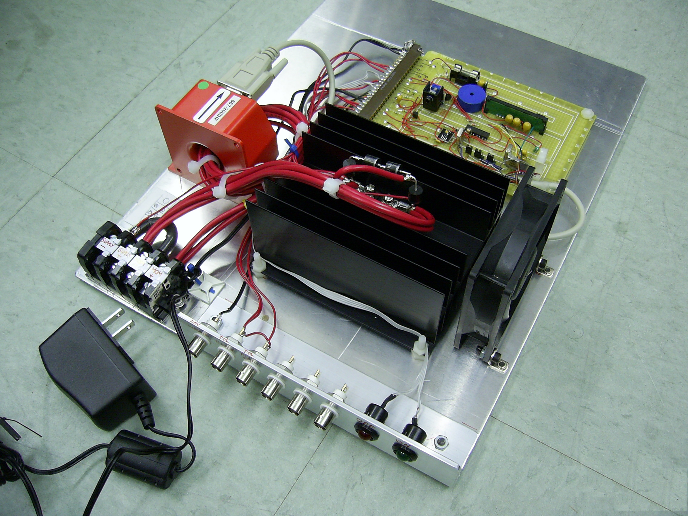
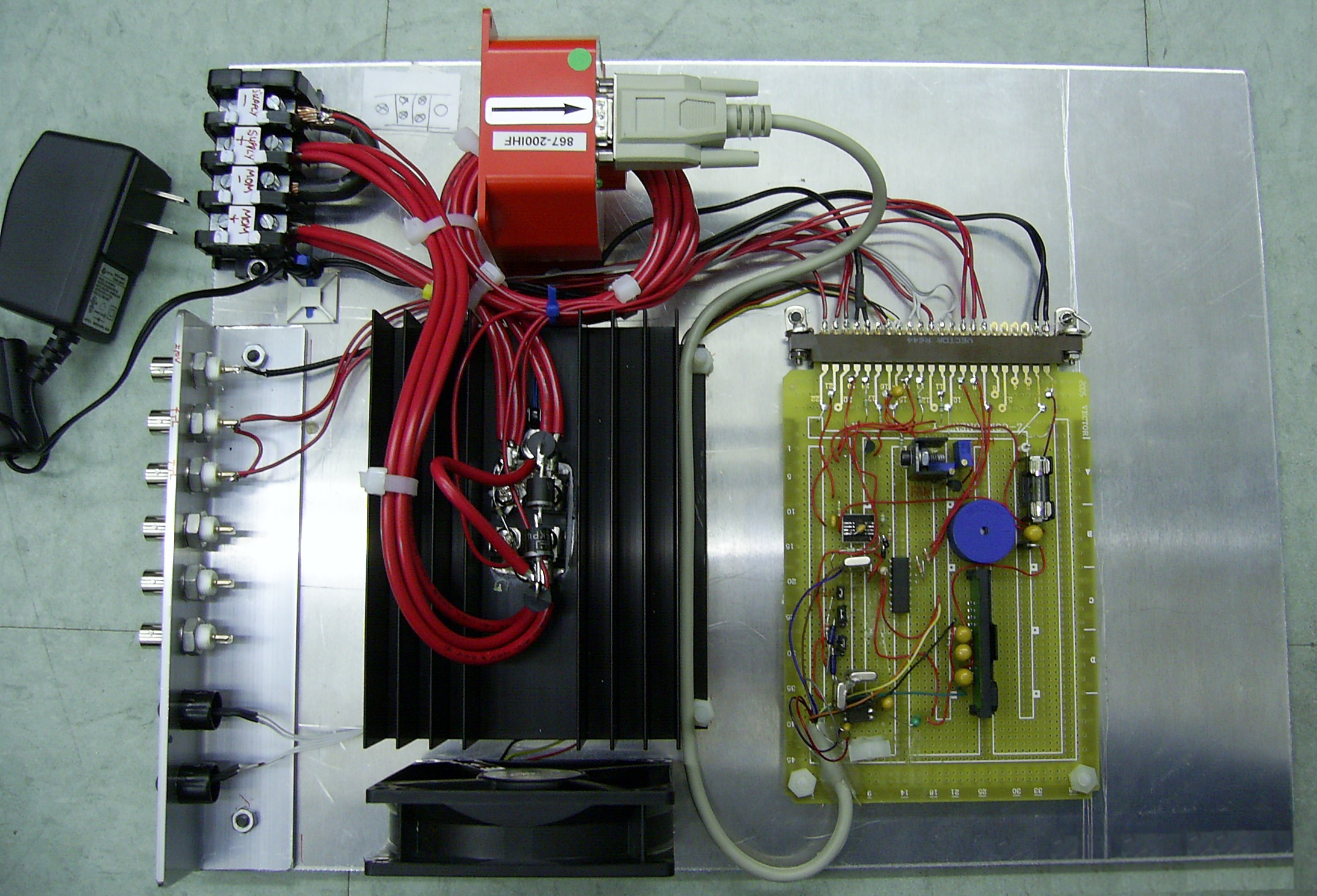
To make a B-field, drive current through a coil. The current is up to 100A and the stability is 10 -5. The C-EMF issue is normal, just control transients and do not break down the control device (FET). The current itself is not a real problem, just use large enough wires to limit losses and be aware of controller dissipation. A side effect is that the coils must be water-cooled. The worst issue is the stability. If the Feshbach resonance region of interest is 0.1% of the absolute coil current, then that region has to be split into 100 sub-regions so that the transitions can be explored. Most of the experiments will be done at around 31A so stability should be around ±300µA.
Power supplies in constant current (CC) mode are ruled out. Nothing was found with that current range and stability for reasonable price. Many power supplies can supply that current with worse specs but in constant voltage (CV) range. The configuration is a honking big power supply (HBPS) in CV mode, a current measurement device, a current controlling device and the closed loop controller. The current controlling device is an IGBT (Insulated Gate Bipolar Transistor, a cross between a FET and a BJT), APT200GN60J from Advanced Power Technology / Micro Semiconductors ; basic specs are 600V 280A 1.4Vsat.
The fun part is the current sensor. How to measure 100A with 10 -5 accuracy? Current sense (AKA Kelvin or 4-terminal) resistors can be found with tempco (TCR) of <1ppm/° but they are not ~2-10mΩ and 20-100W. As resistive power dissipation goes up with the square of current, getting a reasonable voltage from the sense resistor would involve a lot of power loss. Power means heat, heat means resistance change and there goes the accuracy. On top of that, accurate current sense resistors are affected by a power coefficient of resistance (PCR) which may be several times higher, comparing watts to °C.
A current sensor from LEM, the HAIS50-P, was tested. The wire with the current to be measured is passed through a torroid and resultant B-field is measured. Although impressive and cheap, these devices are not stable enough, probably about 10 -3 or 10 -4 accumulated errors. Another device was selected, the Danfysik's Ultrastab 867-200I. This device is similar to the HAIS50-P except that it runs current through windings on the torroid so as to null the B-field, increasing accuracy, stability and cost. Accuracy is not cheap.
The closed loop controller is a regular PID (Proprtional, Integral, Derivative, the standard closed loop configuration);
heavy on the I, weak on the P and D. Initially common emitter was tried but found to be too non-linear, regarding
the error amp output and the coil current. Changing to common collector ("emitter follower") solved that issue.
To avoid having to run the control loop from a higher voltage than the coils, a configuration is used where
the HBPS's +ve output terminal is held at about +2V and the -ve output terminal is driven negative. A circuit
monitors the colector voltage and adjusts the HBPS's CV output so as to keep the IGBT just out of saturation yet
in the linear region. This has the added advantage of minimizing the IGBT power dissipation. In order
to allow fast turning on of the coils, when the IGBT is in cutoff, the HBPS goes to a higher voltage in anticipation
of future needs.
HBPS Supply Settings: Set the HBPS (Honking Big Power Supply) current to greater than 31A, enough so that it always remains in CC (Constant Current) mode. Setting the CC too high is harmless but unsafe in case something fails such as a coil shorting.
Set the HBPS voltage just high enough so that it always remains in CV (Constant Voltage) mode. Simply turn on the Feshbach coils and adjust the supply CV so that it is no more than 1V above the point that it comes out of CC.
WARNING! The supply output terminals must be floating! Grounding either supply terminal will cause improper operation at best and fry something at worst.
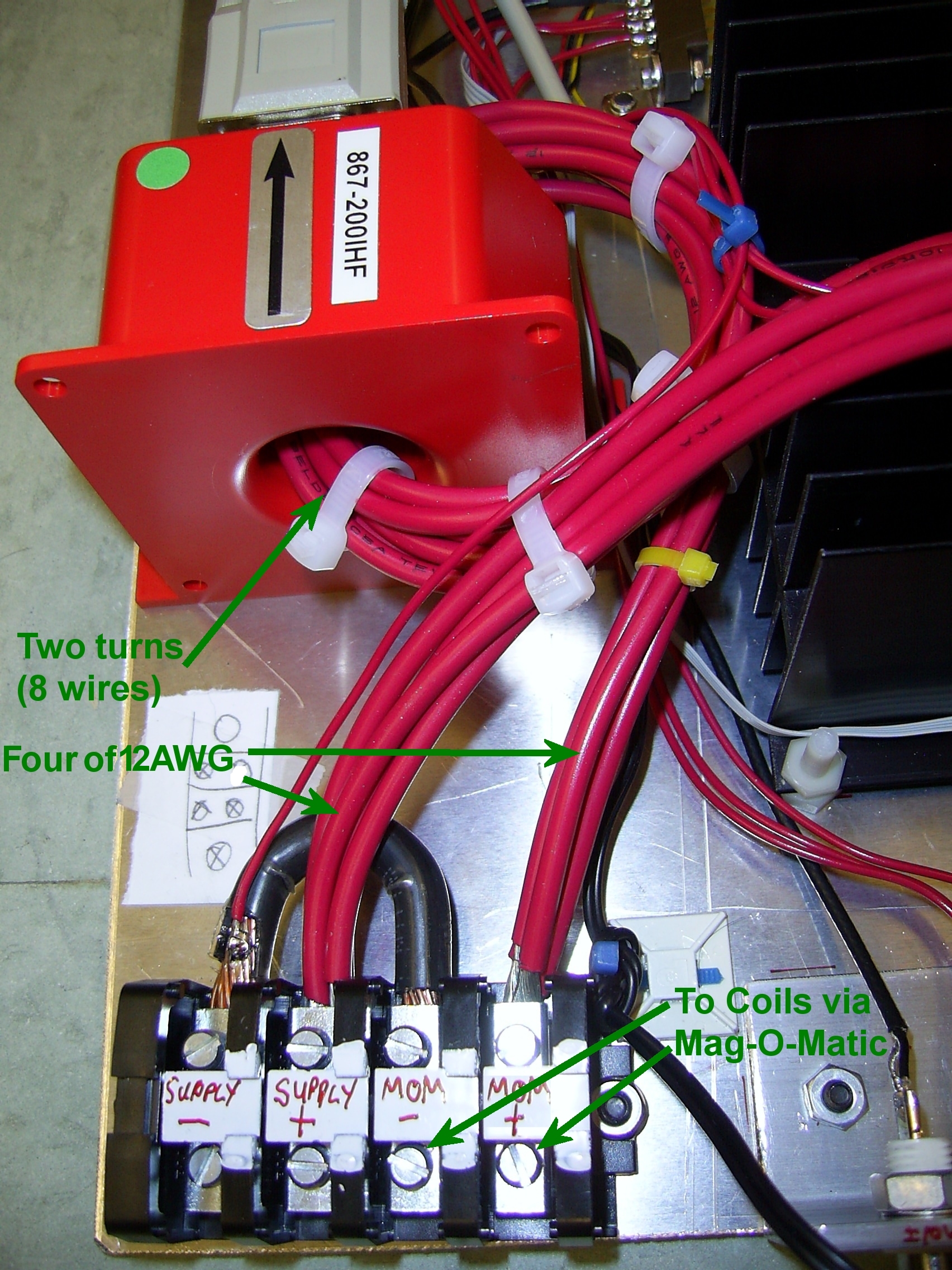
Terminals "Supply+" and "Supply-": Connect the HBPS with 6AWG or similar wire. The supply used is an Agilent 6684A, rated at 40V/128A.
Terminals "MOM+" and "MOM-": Connect the output to the Mag-O-Matic, which routes the controlled current output to the MOT coils. This allows real-time selection for the coils to be connected to the Mag-O-Matic for regular trapping and this Feshbach Coil controller for the precision Fechbach resonance experiments.
BNC "Current": Analog input. A nominal ±10V will give ±300mA on on coil current from the nominal 31.12A, for scanning the Feshbach resosnance region. Normally connected to an ADWin analog output. Can handle up to ±100V and proportional delta current, limited by voltage rating of connectors and wires.
BNC "Enable": TTL input, optically isolated to prevent galvanic ground loops. A logic "1" (>+2.0V) will turn on the coil current to the nominal 31.12A (adjusted ±300mA by the "Current" input). Can tolerate a logic "1" up to +8V; logic "0" is <+1.0V.
BNC "Full On": TTL input, optically isolated to prevent galvanic ground loops. A logic "1" (see "Enable" input for logic levels) will turn the controller fully on so that it is saturated to >110A. This function is to be used if the power supply in CC mode is controlled to set the current. When "Full On", the Feshbach Coil controller can switch up to 100A and will drop approximately 1.5V.
Pot "Fan Temperature" : The IGBT heatsink is cooled by a fan. The heatsink temperature at which the fan will start to turn on at is set by this potentiometer. Normally, it is set to about 40°C; unplug the board, measure the resistance from the thermister terminal to common (AKA Ground) on the board and adjust the pot for 2.50K Ohms. Alternatively, when the heatsink is at the desired temperature, turn this pot until the fan comes on.
Pot "Alarm": If the IGBT heatsink becomes too hot, an annoying audible alarm will sound. The point at which this happens is about 90°C. Causes can be excessive supply voltage (see how to set above), poor air circulation, fan failure. To calibrate, at room temperature, measure the IGBT's V ge (across the "Fan Temp" pot or right on the IGBT terminals), adjust the "Alarm" pot so that the voltage from its wiper to common is 75% of that.
Jumpers: The two 3-terminal jumpers should always be left jumpered to +2.5V (position away from the +2.5V reference). They are there only for future use. The Test jumper when installed will reduce the nominal current from 31.1A to 2.06A for testing.
Grounding: This whole system is dependant on grounding. Adding a ground connection anywhere will make Feshbach resonance impossible. WARNING! The HBPS supply output terminals must be floating! Grounding either supply terminal will cause improper operation at best and fry something at worst.
| Sorry, no more chance for asking direct questions, queries, broken links, problems, flak, slings, arrows, kudos, criticism, comments, brickbats, corrections or suggestions. |
|

|