

|
 Alan Stummer
Research Lab Technologist |

Fesh-MOT Coils
This project is on hold until late 2011 when the experiment can be shut down.
|
Downloads
|
I am curious who uses what. Are these webpages a waste of time, or are they any help to others? Are the circuits, software and utilities appearing in other labs? Please send your comments or suggestions or what you have used (or not) or schematics of your version or pictures or anything! Email me, or be creative and send a postcard! I want to hear from the vacuum! |
Links
|
|
NOTICE: This webpage and associated files is provided for reference only. This is not a kit site! It is a collection of my work here at the University of Toronto in the Physics department. If you are considering using any schematics, designs, or anything else from here then be warned that you had better know something of what you are about to do. No design is guaranteed in any way, including workable schematic, board layout, HDL code, embedded software, user software, component selection, documentation, webpages, or anything. All that said, if it says here it works then for me it worked. To make the project work may have involved undocumented additions, changes, deletions, tweaks, tunings, alterations, modifications, adjustments, waving of a wand while wearing a pointy black hat, appeals to electron deities and just plain doing whatever it takes to make the project work. |
||

Started April 2009 for Chris Ellenor, Adam Weir and Rockson Chang in Aephraim's lab but abandoned for unknown reasons, restarted in June 2011. The "Fesh-MOT Coils" are a pair of coils in series used for both MOT (Magneto-Optical Trapping) and Feshbach resonance . When used for a MOT, the coils are in anti-Helmholtz (magnetic null at the centre) while current is varied between zero and 200A in a profile controlled by the experiment's real-time controller. When the experiment is in Feshbach resonance, the coils are in Helmholtz (even magnetic field throughout) while current is set at approximately 125A, programmatically set ±250mA and repeatable to <10PPM (10 -5 or ±1mA). Current can be up to 200A but current at high values may be time limited because of thermal restraints and experimental requirements. This project as shown here does not include coil design or construction, only the controls. Note that the Feshbach current may be changed after empirical testing.
The basic blocks are a 5KW/200A/25V power supply to source raw power, the pair of coils, a relay (or pair) to switch between Helmholtz and anti-Helmholtz, a power FET on a heatsink, a precision current sensor and various control inputs. The control inputs come from the experiment's central real-time controller. The control inputs include whether in MOT or Feshbach mode, whether in Helmhotz or anti-Helmholtz configuration, an analog voltage to set the coil current according to the MOT or Feshbach mode plus a couple more minor controls.
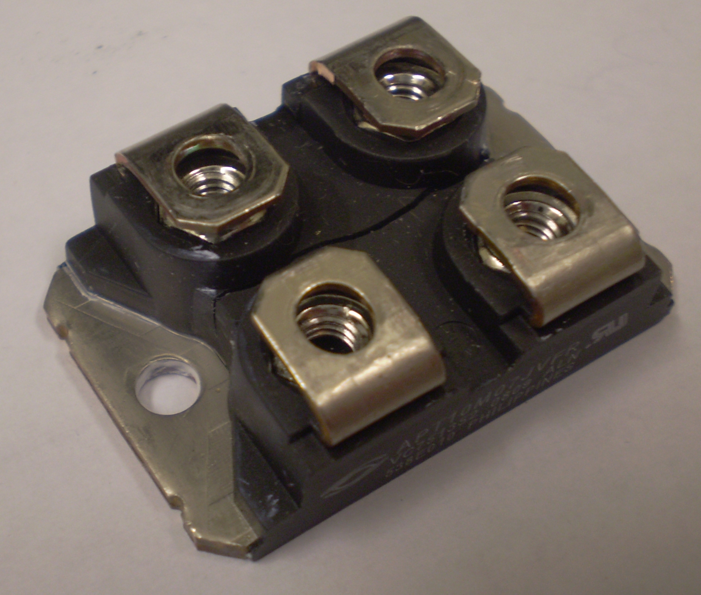
The heart of the unit is LEM's UltraStab IT-200-S/SP2 current sensor ( installation and dimensions). The UltraStab refers to ultra-stability, not some psychotic behaviour. Its output current is 0.1% of the coil current, so at 125A it outputs 125mA. This current goes through a low tempco 10 Ohm burden resistor, so 125A appears as 1.25V. This is compared to either an externally provided voltage (MOT mode) or a local precision voltage (Feshbach mode). In the latter Feshbach case, the reference is based around a low tempco Thaler VRE3025A +2.5V reference. This +2.5V is dropped by low tempco Vishay's Z20x- series resistors to +1.25V, adjustable by up to ±7.6% in setup and ±250mA in operation. A TTL input selects between the two operation modes. These two voltages (feedback and reference) are compared with an AD8067AR opamp with PI (Proportional and Integral) gain. The output drives the gates of three parallel Microsemi APT20M11JVR (or similar) power N-FETs in a common Source configuration. The coils are connected to a large power supply and the Drains.
Ensure that the large power supply is floating, then connect its negative terminal to the FETs' Source terminals after passing through the current sensor, its positive terminal to the coils and relays and finally the other side of the coils and relays to the FETs' Drains. Do not connect any other part of the supply or coils to anyhting else. Connecting any of those to a ground will cause smoke to be generated and much chafing. Connect TTL inputs as required: they are isolated and will not change the system's grounding. Connect an analog control to the Set Current input.
Current limit the power supply to several amps and set it to +8-10V. Turn on the unit and the power supply. Apply about +100mV to the Set Current. Approximately 1A should flow. If the current suddenly shoots up to the current limit, the current sensor is backwards. Gradually increase the current limit and set current but always be aware of the FET power dissipation as described below in the warning. Refer to that section on how to setup the power supply for MOT and Feshbach modes. Always be aware of FET power dissipation or you will become an expert in replacing them!
Although common Source configuration of the FETs does have advantages (flexibility in the large power supply voltage and ganging, limitation in Gate drive voltage, inability to breakdown the gate, etc.), a problem is that the loop gain depends on the FETs' I d vs V gs transfer curves. This is most noticable at low currents. To correct for this, monitor the coil current with a current clamp such as AEMC's MR461. Ramp the current up then down from zero to about 25A p while watching for high frequency oscillations in the coil current. If oscillations occur, adjust the power supply voltage up or down until the current is stable in its ramp, as shown pictures 6-10 in this series of tests. The power supply voltage may have to be dynamically changed during current changes to prevent oscillations and from burning the FETs.
This section will be available later.
Helmholtz Relay Warning
Do not change the Helmholtz mode (AKA change the Helmholtz Relay input from high to low or low to high) when there is any current flowing in the coils. Due to their inductive nature, any coil current interrupted by the relay switching will cause a high counter-EMF and arc the relay contacts. This will damage the contacts and possibly burn them out or make them unreliable.
The FETs control the coil current. The power dissipation is the product of coil current times the voltage drop across the FETs. The higher the power, the greater the heat it dissipates and the higher the FETs' junction temperature. Short bursts of less than a couple of seconds are acceptable. Sustained currents and FET voltage drops cause increased FET temperature. Although fans will turn on to cool the FETs, they can only do so much. Be aware of the FETs and their heatsink temperatures.
In MOT mode, the simplest method to lower FET power and temperature is to request full current so as to saturate the FETs but to run the power supply in constant current (CC) mode.
In Feshbach mode the FETs must be kept out of saturation so that they can regulate the current. To minimize
the FETs' power and temperature, measure the voltage drop across the FETs (measure right on the FETs' terminals
so to exclude wiring losses) while operating in Feshbach mode, then adjust the power supply's voltage
so that the FET voltage drop is just above its saturation voltage. To measure the saturation voltage,
put the supply in CC mode at the desired current, request more than that from the Fesh-Mot and measure the
FET voltage. It will be 1-2V depending on the FET used.
| Parameter | Value | Comments |
| MOT current range | 0 to 200A | |
| MOT turn-off speed | -0.68A/uS typ | Current slew rate using Step Down control |
| Feshbach current | 125A nom | Adjustable ±7.6% by jumpers and trimpot |
| Feshbach linear adj range | ±25mA typ | |
| Feshbach repeatability | ±1mA max | At 25º ±5° |
| Feshbach tempco | ±0.6ppm/° max | Max, limited by reference voltage |
| Coil inductance | 400uH typ | Total, as installed, including mutual inductance |
| Coil resistance | 63mOhm typ | Total, as installed, 25° |
| Parasitic resistance | 70mOhm typ | Total wiring, excluding coils and FETs |
| Input | Value | Description | |
| Current Control | MOT mode | 0 to +10V | 13.64A/V, set to -0.1V to ensure fully off |
| Feshbach mode | ±10V | ±250mA | |
| Current control mode | TTL 1 | 0 = MOT mode
1 = Feshbach mode |
|
| Relay drives | TTL 1,2 | 1 = relay on | |
| 2A | 12V resistive or inductive load | ||
| Offset +¼A 3 | TTL 1 | 1 = adds ~250mA for Feshbach mode | |
| Step Down 4 (AKA Fast Off) | TTL 1 | 0 = normal operation
1 = off (at -800A/mS typ) for MOT mode |
|
|
Note 1: TTL: low <0.7V, high > 2.5V, 5V max, load is 274 Ohm & optocoupler LED
Note 2: Never ever switch relay inputs when there is any current flowing in the coils! Note 3: To approach Feshbach resonance from above Note 4: Current will step down fast by several amps, step size is not controlled, measure empirically |
|||
Return to homepage
| Sorry, no more chance for asking direct questions, queries, broken links, problems, flak, slings, arrows, kudos, criticism, comments, brickbats, corrections or suggestions. |
|

|