ALPS - AOM Laser Power Stabilization

|
||
|
Downloads
|
I am curious who uses what. Are these webpages a waste of time,or are they any help to others? Are the circuits, software and utilities appearing in other labs? Please send your comments or suggestions or what you have used (or not) or schematics of your version or pictures or anything! Email me, or be creative and send a postcard! I want to hear from the vacuum! |
Links
|
|
NOTICE: This webpage and associated files is provided for reference only. This is not a kit site! It is a collection of my work here at the University of Toronto in the Physics department. If you are considering using any schematics, designs, or anything else from here then be warned that you had better know something of what you are about to do. No design is guaranteed in any way, including workable schematic, board layout, HDL code, embedded software, user software, component selection, documentation, webpages, or anything. All that said, if it says here it works then for me it worked. To make the project work may have involved undocumented additions, changes, deletions, tweaks, tunings, alterations, modifications, adjustments, waving of a wand while wearing a pointy black hat, appeals to electron deities and just plain doing whatever it takes to make the project work. |
||
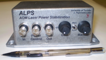
Started June 2008, for Julie Sutton in Joseph's lab. This project controls the laser power delivered to the experiment. Contrary to its lumpy namesake, ALPS also removes peaks and valleys from the beam. A laser, or part of a beam, is sent to an AOM. The AOM's "walking wave" diffracts part of the beam out at an angle - the 1 st order beam. The amount of light diffracted is roughly proportional to the RF power, creating our working output. A photodiode taps a bit of this light. The amplitude of the RF is adjusted by the ALPS such that the desired power is obtained. To reduce effects of upstream polarization changes, a polarizer may be inserted after the AOM but before the photodiode and experiment.
The RF is generated by an AOM driver module, Crystal Technology's 1080AF-AIFO-2.0. It is fixed at 80MHz with amplitude control (AM) from zero to 2W. The ALPS provides a 0V to +1V input to the driver's AM input. The photodiode is Thorlabs DET36A, an amplified Si photodiode.| Parameter | Conditions | Specification | AbsMax (2) | ||
| (with +24V supply) | Min | Typ | Max | ||
| Amplified PD Range | 0V | +2.5V | ±5V | ||
| Power Control input | -0.1V | +10V | ±15V | ||
| Modulation Output, manual mode | 50 Ohm load | 0V | +1.0V | ||
| Modulation Output, automatic mode | 50 Ohm load | 0V | +1.0V | ||
| Gain range | 24:1 | ||||
| Supply voltage | Excluding AOM driver | +22V | +24V | +30V | +35V |
| Supply current (1) | Excluding AOM driver | 20mA | 45mA | 50mA | |
The amplified photodiode feedback, the PD Input BNC, is terminated into 50 Ohms. The feedback is compared to the setpoint voltage from the Power Control BNC then the result is integrated. The integrator output, the Mod Out BNC, goes to a 50 ohm load on an AOM driver module. A switch selects this integrator output (automatic mode) or a potentiometer (manual mode) for setup.
If the loop cannot supply the requested optical power for any reason, the servo opamp will go close to the positive
supply rail. That condition turns on a warning LED and sounds a buzzer for a few seconds.
| Sorry, no more chance for asking direct questions, queries, broken links, problems, flak, slings, arrows, kudos, criticism, comments, brickbats, corrections or suggestions. |

|