

|
 Alan Stummer
Research Lab Technologist |
|
|
"Schlosser" Laser Lock |
|

Downloads
|
I am curious who uses what. Are these webpages a waste of time, or are they any help to others? Are the circuits, software and utilities appearing in other labs? Please send your comments or suggestions or what you have used (or not) or schematics of your version or pictures or anything! Email me, or be creative and send a postcard! I want to hear from the vacuum! |
Links
|
|
NOTICE: This webpage and associated files is provided for reference only. This is not a kit site! It is a collection of my work here at the University of Toronto in the Physics department. If you are considering using any schematics, designs, or anything else from here then be warned that you had better know something of what you are about to do. No design is guaranteed in any way, including workable schematic, board layout, HDL code, embedded software, user software, component selection, documentation, webpages, or anything. All that said, if it says here it works then for me it worked. To make the project work may have involved undocumented additions, changes, deletions, tweaks, tunings, alterations, modifications, adjustments, waving of a wand while wearing a pointy black hat, appeals to electron deities and just plain doing whatever it takes to make the project work. |
||

Disclaimer
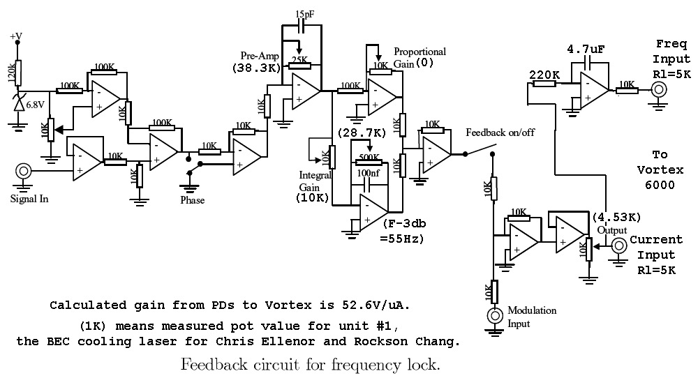
This is not my design. It is based on assorted segments of schematics from lab books and pieces of paper and verbal descriptions. If I was to design this from scratch it would be quite different, simpler and work better but the request was to keep it the same - status quo rules. Therefore, the transfer functions have not been changed at all, with one exception (the low frequency rolloff frequency is now separated from the original contorted combination of frequency and gain in one trimpot and another to counteract the gain change). That said, gains have been brought into realistic regions per stage, gains have been balanced between stages, amplifier impedances were brought into practical values, input protection was added for both ESD and with power off, amplifiers have had reasonable upper frequency limits added for stability, supplies were bypassed properly, ground planes added, power supply returns now deterministic, photodiode amplifier grounding corrected, overall grounding scheme implemented, supply fuse added, test points added for measuring trimpot settings, equations given to calculate parameters then to be able to set them on the trimpots, indicator LEDs added to quickly diagnose lock state, internal triangle oscillator added for scanning, front panel polarity switch added to allow easy changes between rising and falling edges of spectrum, etc.
Started Jan 2009 for Chris Ellenor and Rockson Chang in Aephraim Steinberg 's lab. This is a rebuild of an existing circuit . The duct tape and staples are wearing out, time to make a new one. Some modifications have been made to the original circuit.
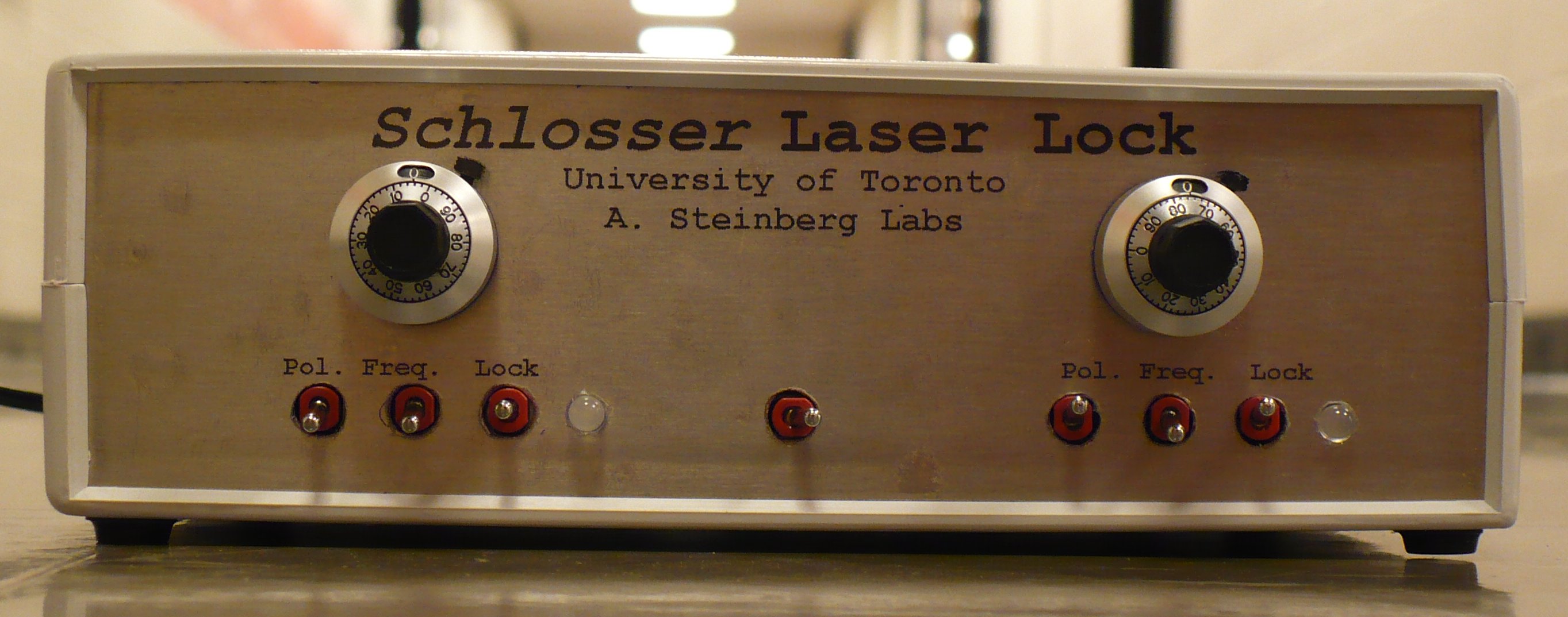
The Schlosser (ger: lock-er) is a dual laser lock box. For each channel, a laser uses the saturated absorption of a Rb or K vapour cell to detect specific absorption lines and therefore a specific wavelength. Active feedback further narrows the laser line width. Each channel has a wideband proportional gain amplifier, a limited bandwidth amplifier and a slower integrator, plus a front panel setpoint control, both going into a Vortex laser controller. For setup, a 4Hz triangle oscillator injects a signal into the Vortex while an oscilloscope monitors the resulting absorption spectrum. Setup is required many times during the experiment.
The input stage can be configured as a transimpedance amplifier (TIA) for raw photodiodes, or as an inverting voltage amplifier for use with amplified photodiodes. The front panel pot adds an offset to determine the part of the absorption slope to lock to. The next stage is selectable by a front panel switch for inverting or non-inverting, to select rising or falling edges of the absorption curve. That signal is split to a full bandwidth path and a limited bandwidth path. In the latter, the -3dB frequency is adjustable with a trimpot. Both paths' gains are trimpot adjusted. In normal locked mode - as selected by the front panel switch - this resultant error signal is sent to the Votex's laser current input. It also goes to an integrator which drives the Vortex's laser frequency input (a piezo on the grating of the external cavity laser). This integrator polarity is jumper selectable, so that the Vortex's current and frequency inputs can be in or out of phase.
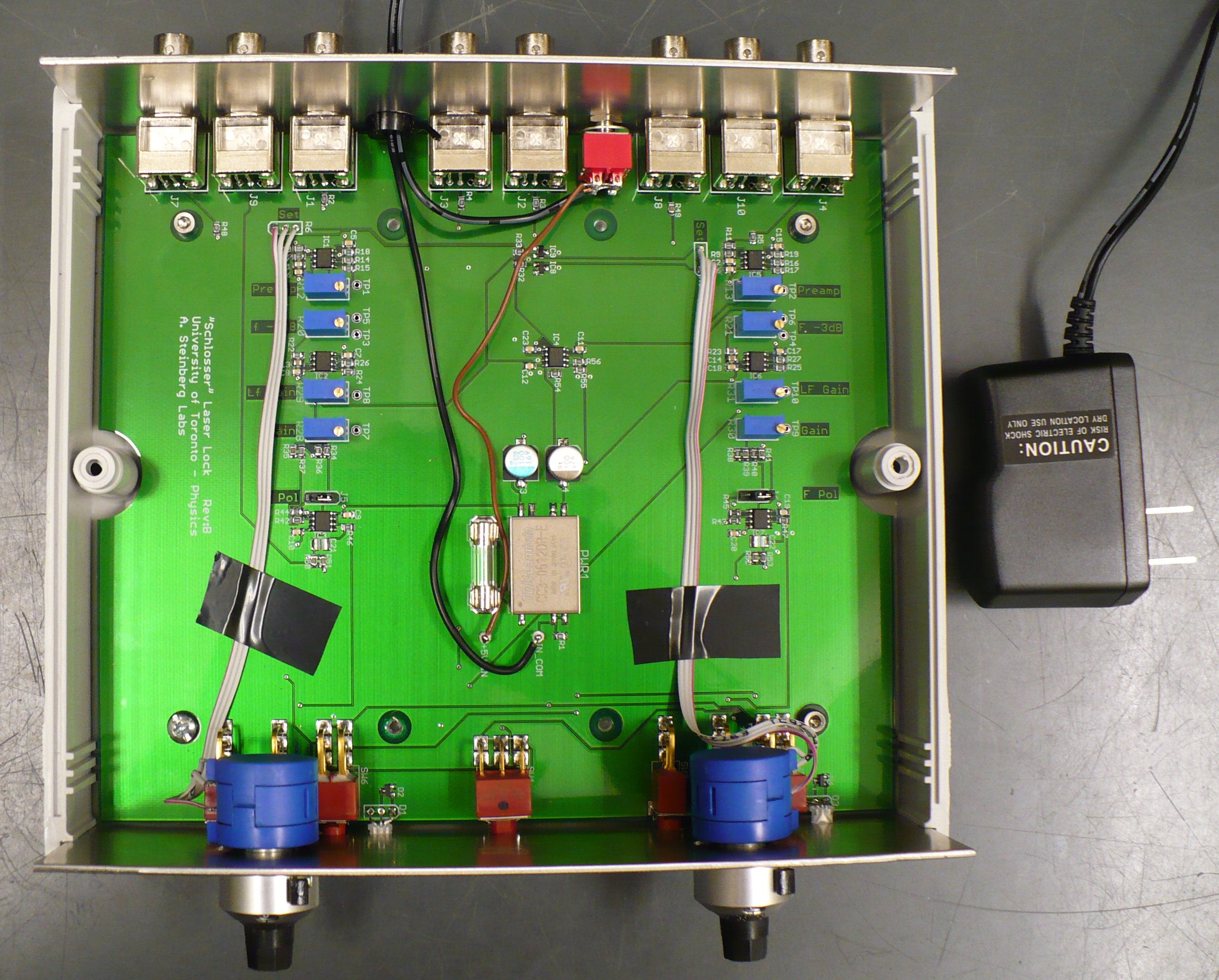
Each trimpot has one or two testpoints (TP) beside it. If a single TP, turn off the power and measure resistance to the ground plane. For two TPs, turn off the power and measure the resistance between the two TPs. Be sure to turn off the power before measuring resistance or you may toast the meter or the board.- Decide on a rolloff frequency and set it as shown below. Try something in the audio range, maybe 1KHz? or set frequency pot full CCW (58Hz) then raise later.
- Turn the Preamp gain clockwise to full. Turn the Gain CCW to zero and Low Frequency Gain CCW then a few turns up to give a little gain. Roughly centre the front panel Setpoint control.
- With Frequency Lock off and in Calibrate ( Lock switch is down), adjust the Vortex laser controller, the front panel Setpoint and the 'scope for a reasonable optical transition.
- Turn the lock on (Lock switch up) with the frequency lock off. Slowly turn up the LF Gain until the laser locks. Select a place on the absorption spectrum with the Setpoint control. Turn up the LF Gain until everything starts to oscillate then back it off by a significant amount (~25-50%?). Now turn up the Gain trimpot until it oscillates again then back off again to keep it very stable. Better too little gain than too much!
Note that the loop gain depends on the slope of the lock point so that changing to a different setpoint on a different mode with a steeper slope may cause the system to oscillate. Simply turn down the Preamp gain to make it very stable again.
| Trimpot | Setup |
| Preamp | Approximate normalized gain is resistance / 8K. The "8K" value may be determined a bit better by setting it to full gain and measuring resistance. |
| Frequency -3dB | Measure R between the two TPs. f(-3db) = 1 / (2Pi * (R+2000) * 56e-9), in Hz, range is 28Hz to 1.5KHz. |
| Gain | For both trimpots, approximate normalized gain is resistance / 8K.
At frequencies above the -3dB frequency, the gain is only as set by the "Gain" trimpot. This will help reduce shot noise from the laser. At frequencies below the -3dB frequency, the gain is the sum of the two trimpots. This additional gain boost at low frequencies reduces mechanical noises. |
| Low Frequency Gain | |
| Frequency Polarity | This jumper selects the direction of the frequency integrator. If correct, everything works. If backwards, the integrator will immediately lock up (and light the frequency error LED) when the frequency lock switch is turned on. The Vortex 6000 appears to want the Laser Current and the Laser Frequency inputs to be opposite polarity (while one goes positive, the other goes negative), although this is not confirmed in the datasheet. |
- Turn off Frequency lock, switch to Calibrate (Lock switch down).
- Adjust the Vortex laser controller for the desired part of the spectrum. Note exactly where on the 'scope X-axis you want to lock. Adjust the Setpoint for that lock point to cross zero.
- Set to Lock (switch up). The 'scope spot should jump sideways to a point. It could be the wrong crossing (slope) so adjust the Setpoint to force it to the correct crossing. If still wrong, change the Polarity switch to lock to the inverse slopes and adjust the Setpoint again.
- Turn on Frequency lock. The 'scope dot should never go above or below zero. If the laser drifts over minutes or hours, the frequency lock will correct it. After significant corrections, the red/green LED will start to come on. When bright, you will have to calibrate the setup again.
Return to homepage
| Sorry, no more chance for asking direct questions, queries, broken links, problems, flak, slings, arrows, kudos, criticism, comments, brickbats, corrections or suggestions. |
|

|