

|
 Alan Stummer
Research Lab Technologist |

Shim Coils, an add-on to CATS2
|
|
|
|
Downloads
|
I am curious who uses what. Are these webpages a waste of time, or are they any help to others? Are the circuits, software and utilities appearing in other labs? Please send your comments or suggestions or what you have used (or not) or schematics of your version or pictures or anything! Email me, or be creative and send a postcard! I want to hear from the vacuum! |
Links
|
|
NOTICE: This webpage and associated files is provided for reference only. This is not a kit site! It is a collection of my work here at the University of Toronto in the Physics department. If you are considering using any schematics, designs, or anything else from here then be warned that you had better know something of what you are about to do. No design is guaranteed in any way, including workable schematic, board layout, HDL code, embedded software, user software, component selection, documentation, webpages, or anything. All that said, if it says here it works then for me it worked. To make the project work may have involved undocumented additions, changes, deletions, tweaks, tunings, alterations, modifications, adjustments, waving of a wand while wearing a pointy black hat, appeals to electron deities and just plain doing whatever it takes to make the project work. |
||

Started March 2010 for Joseph's lab. A group of up to 11 coils adjust for slowly varying ambient magnetic fields and sometimes do some work in manipulating cold atoms. See the CATS2 project for details of the overall project.
Break any of these rules and you face my wrath and a broken Shimmer! In no particular order:
- Do not ground the coil power supply/supplies except for a single 22AWG wire from the negative bus to an earth.
- Do not connect the controller's Saturation or Temperature BNCs to anything grounded, such as a 'scope.
- Do not burn out FETs by using excessive voltage on the coil power supply.
- Do not unplug a coil from the power box front panel BNC while it is carrying current.
- Channels can be put in parallel, the coil current will be the sum of the settings. No limit to parallelism other than the obvious 11.
- Above mentioned wrath is negligible. Repairs will be done by user whenever possible.
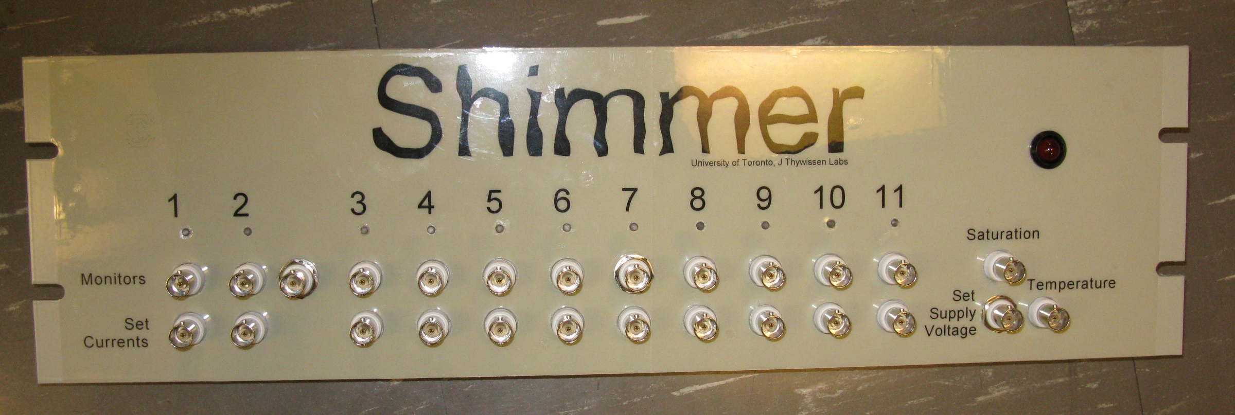
Shimmer has two distinct sections: the 19" rack mount controller and the half-rack power box . A copy of the existing CATS2 controller board is used as is, except for faceplate labelling. Inside the power box, the current sensors and FETs handle much lower currents than CATS2. See the CATS2 project for details of how they work.
In summary, all channels are almost identical. The coil is connected to a power supply in CV (Constant Voltage) mode. A FET in common source configuration adjusts current flow through the coil and back to the power supply. On the drain side of the FET, the wire carrying the coil current from the power box's from panel banana jack passes through a current sensor . This sensor is connected to the controller baord with a 0.75m DB9 cable. The controller powers the sensor with ±15V. A 0-4V feedback signal from the sensor covers the 0-5A range. An opamp compares the current feedback to a setpoint given by the controller's front panel BNC and adjusts the FET's gate accordingly to maintain the desired current. The current feedback is also sent to another controller front panel BNC for monitoring. Both the setpoint and current monitoring connectors are galvanically isolated from the power box circuits.
The only difference between channels is that channel 2 has a BNC with TTL input to turn off the current immediately. This necessitates bypassing the channel 2 FET with a TVS (Transient Volatage Suppressor) to prevent it from avalanching (a possibly harmful form of drain-source breakdown).
Setting The Coil Supply Voltage
An important consideration is power dissipation of the FETs in the power box. Maintain as low a coil power supply voltage as practical without saturating any FETs. The large red LED on the controller lights when any FET becomes saturation, indicating that at least one coil is not at its set current. Also, the controller's "Saturation" BNC will indicate the lowest FET voltage, indicating how close to saturation the FETs are. Adjust the coil power supply voltage to keep the monitored Saturation voltage as low as practical. Note that the Saturation BNC connector is at the power box voltage and must not be grounded such as through a scope!
A fan on the power box will kick in as the heatsink warms up. The controller's front panel "Temperature" BNC monitors the heatsink in the power box. The NTC thermister is carried on the DB9 cable for channel 1 so that channel must laways be used! Note that the Tempoerature BNC connector is at the power box voltage and must not be grounded such as through a scope!
| Parameter | Conditions | Value |
| Number of shim coils | 11 | |
| Shim coil maximum current | Continious, per coil | 5A |
| "Off" leakage | <100uA max | |
| Coil resistance | 3 Ohms typ | |
| Maximum total current | 55A | |
| Maximum coil supply voltage 1 | 50V |
| Sorry, no more chance for asking direct questions, queries, broken links, problems, flak, slings, arrows, kudos, criticism, comments, brickbats, corrections or suggestions. |
|

|