I am curious who uses what. Are these webpages a waste of time, or are they any help to others? Are
the circuits, software and utilities appearing in other labs? Please send your comments or suggestions
or what you have used (or not) or schematics of your version or pictures or anything!
Email
me, or be creative and send a
postcard! I want to hear from the vacuum!
NOTICE: This webpage and associated files is provided for reference only. This is not a kit site!
It is a collection of my work here at the
University of Toronto in the
Physics department. If you are considering using any schematics, designs, or anything else from here then
be warned that you had better know something of what you are about to do. No design is guaranteed in any
way, including workable schematic, board layout, HDL code, embedded software, user software, component selection,
documentation, webpages, or anything.
All that said, if it says here it works then for me it worked. To make the project work may have involved
undocumented additions, changes, deletions, tweaks, tunings, alterations, modifications, adjustments, waving
of a wand while wearing a pointy black hat, appeals to electron deities and just plain doing whatever it takes
to make the project work.
Overview
Started August 2009 for
Joseph Tywissens'
labs, the CATS2 is a remake of the original
CATS. This overall design was given to me, it is not the way I would do this. Do to the resulting complexity,
grounding issues, the overly repetative nature of the channels, the discreet analog control inputs and various other
issues, I would not recommend using this overall design. See the
disclaimer
below.
In the fermion lattice experiments, a
40K MOT is created in a relatively high pressure chamber (~10
-8 Torr). The atoms are
cooled with lasers
and other techniques to several µK (AKA -273°C). The cloud of cold atoms is then transfered to the lower pressure
(~10
-10Torr) experiment chamber. This transfer is done with a series of coils as shown in the animation above.
Eighteen sets of coils are required, each coil current quickly running up and down to create a moving magnetic
null, the atoms' trapping point. The end to end transfer should take 1-2 seconds. A small "wall wart" supply
powers the circuitry. A conglomerate of three paralleled
HP6296B supplies (40V/50A each) and possibly a supercap power the coils.
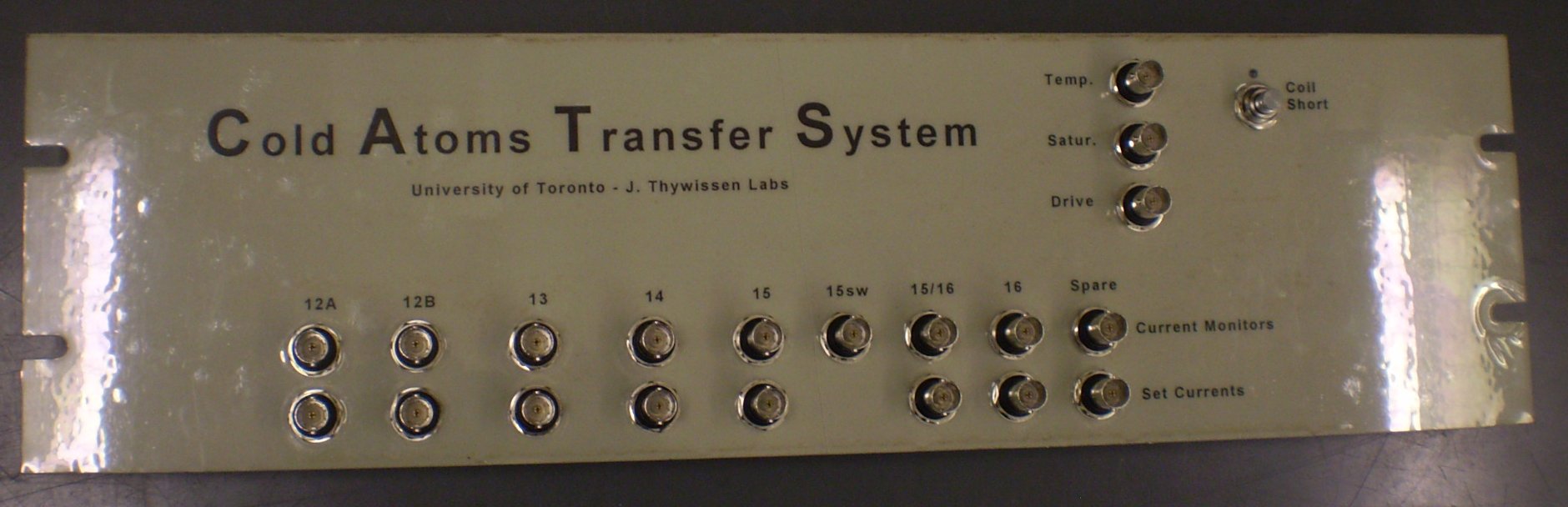
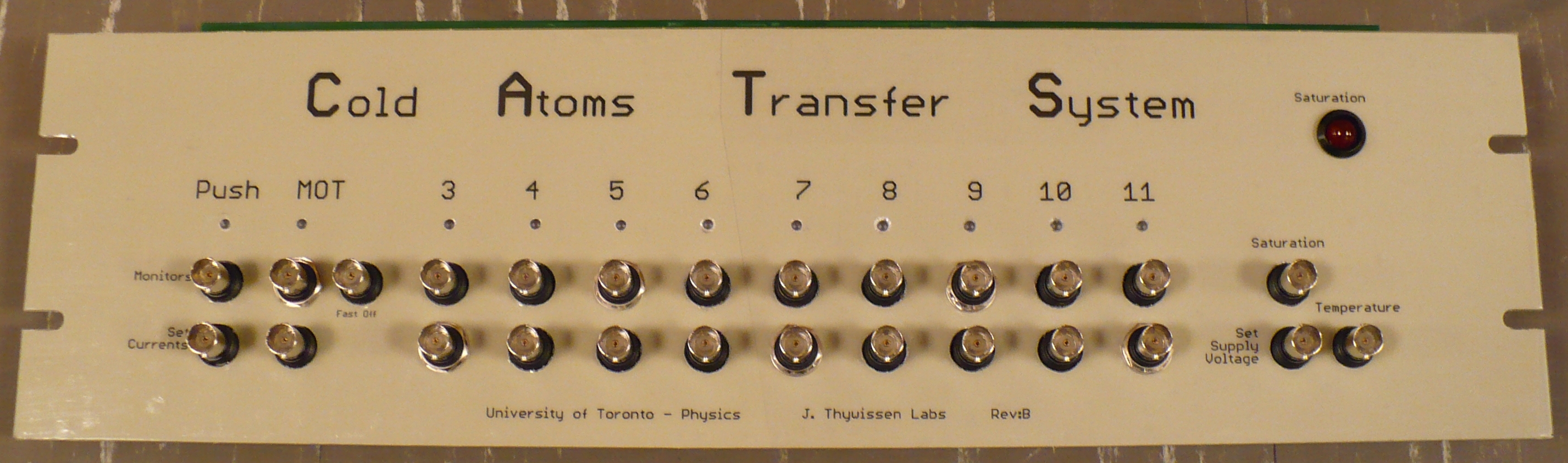
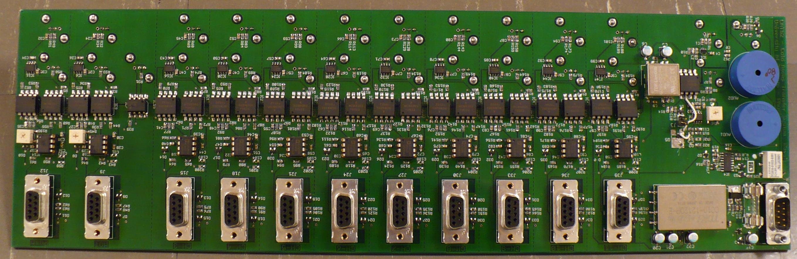
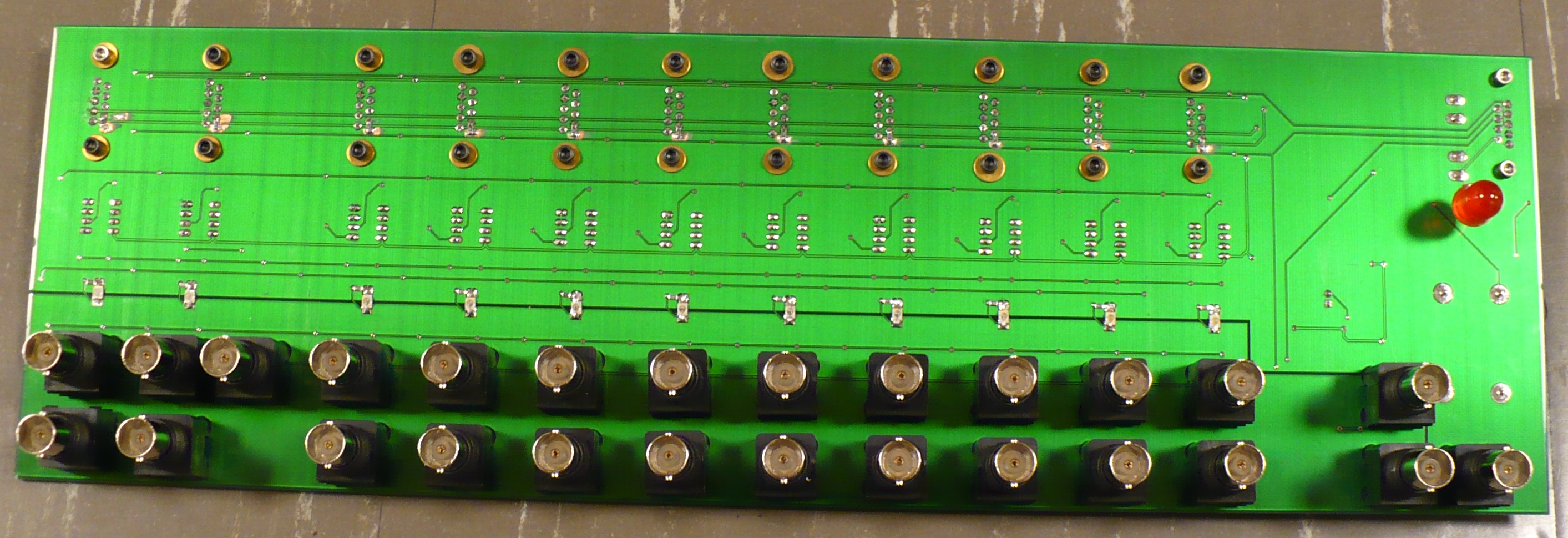
CATS2 is built on two PCBs and heat sink assemblies: one set for the MOT and horizontal transfer up to but not including
the corner, the other set for the vertical transfer and quadrapole. Each PCB fits a 3U 19" rack. The heatsinks
are custom machined aluminum plates with water cooling.
Disclaimer
If you are considering making this project or basing your transfer on it, think twice. This overall structure is
not my choice, it was required by the lab and later expanded on by a visiting post-doc. It has become a comittee
design: cumbersome and overcomplicated. Presently, the currents profile LUT (Lookup Table) are downloaded
to an external controller which sends 20+ analog signals to the CATS2, each one galvanically isolated plus provide
galvanically isolated monitoring of each channel's current. My preference would be to download the LUT directly
to CATS(2) then have it directly drive each channel. Current monitoring would be sent back via ethernet, but
only current error need be sent. Strategically, I would have used a single microprocessor (µC) to run multi-channel
DACs which set individual currents, with the µC communicating over UDP/IP to get the current profiles and a single
TTL input to start the sequence. Current monitoring - if insisted on, besides being redundant - could have been returned
over IP. The µC could have controlled the supplies to minimize FETs dissipation, plus calculated coil temperatures
on the fly and shut them down before the coils are damaged or destroyed. The simple analog method that is used
instead has been insisted on by the end users.
Welcome to the 20th century!
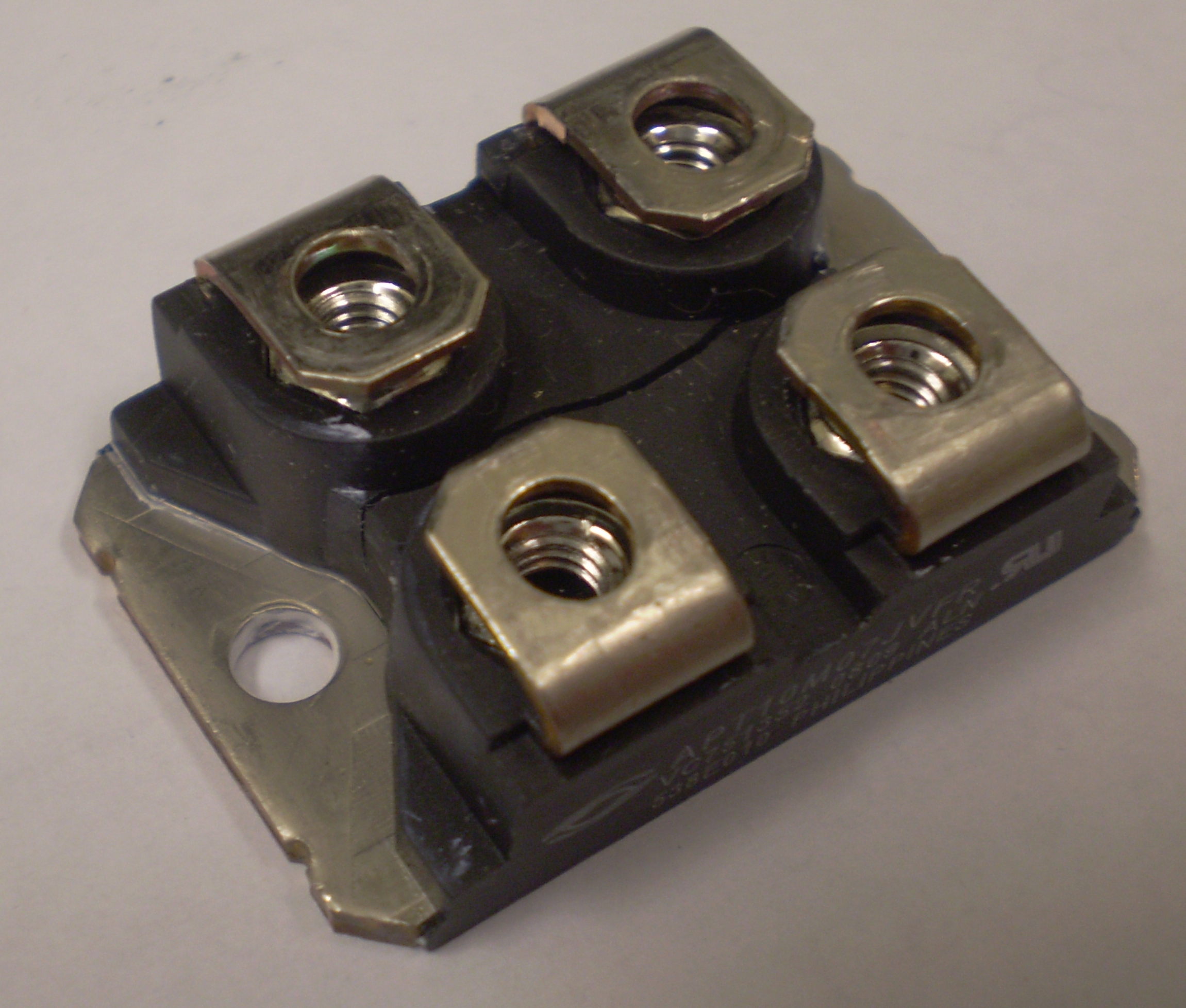
* Heat Warning *
A lot of power is available to the coils but they are meant to be on for only a short time. If on for too long then
the coils could melt their insulation, the CATS could burn out a power FET, or both. Always ensure that coils are
not left on for longer than intended! Burning coils and/or FETS will void the non-existant warranty!
Here is what happens if you overheat a FET.
* Grounding Warning *
A lot of current flows through the CATS2. Improper grounding will burn out coils, the CATS2 and/or external equipment
such as the ADWin controller! This is not a possibility, it is a probability! Ensure that the CATS2 and its power
supplies are totally floating except for a single wire connecting the supplies' negative rail to earth, for safety. The
control side ground can be through the analog inputs coming from the ADWin.
Specifications
Parameter
Conditions
Min
Typ
Max
Notes
Number of unipolar coils
16
Number of bipolar coils
3
Specs apply equally to either polarity
Current per coil
Exclusive of thermal issues
100A
"Push" coil is 150A peak
Total instantaneous coil currents
Exclusive of thermal issues
150A
May be increased with ultracaps
Coil off leakage
At 25°
0.25mA
FET dependant, using APT10M07JVFR
Coil Supply
2V
10V?
100V
May be increased with other FETs/IGBTs
Control input for zero coil current
Horizontal transfer
+30mV
+38mV
+46mV
To provide dead band at zero
Vertical transfer, unipolar
+10mV
+13mV
+15mV
Vertical transfer, bipolar
±10mV
±13mV
±15mV
Channel 15/16
+90mV
+114mV
+138mV
Coil current with +10V control input
Scale x1.5 for "Push"
92.7A
99.8A
106.9A
Error dominated by current sensor
Coil current tempco at 1A
-25mA/°
±0mA/°
+25mA/°
Dominated by current sensor
Coil current tempco at 100A
Scale x1.5 for "Push"
-108mA/°
-6.5mA/°
+94mA/°
Dominated by current sensor
Current monitor output at 100A
Vert: 150A for "Push"
+9.42V
+9.92V
+10.44V
WRT actual (not Set) coil current
Step response, 0.1A to 100A
10% to 90%
23uS
From simulations only, resistive load
Step response, 100A to 0.1A
90% to 10%
23uS
From simulations only, resistive load
Unipolar Channels 1 to 12A (& 16)
Each unipolar channel is independantly capable of supplying from zero to 100A to its coil(s). Total current never exceeds
approximately 150A. Each channel is typically on for much shorter than one second, following a roughly Gaussian or triangular
shaped current profile. Channels overlap but never more than four are on at any instant.
As implied by "unipolar", these channels can supply current in only one direction through their coils. The analog
input voltage controls the current, from 0A to 100A. Input voltages less than +38mV will shut off the current, however
inputs above +10V will continue to increase the current until the coil power supply limits by its voltage or current
limits.
High power FETs such as
Microsemi's APT10M7JV (700W) is a low side linear controller. Due to the relatively low tolerance requirements
and reasonable loop gains, the FETs can easily be substituted or even possibly replaced by IGBTs. Current monitoring
and feedback is from
LEM's
HAS-100/200-S
Hall effect device.
Bipolar Channels 12B, 13, 14 (& 15)
Each bipolar channel is independantly capable of supplying from -100A to +100A to its coil. Total current never exceeds
approximately 150A. Each channel is typically on for much shorter than one second, following a roughly Gaussian
shaped current profile. Channels overlap but never more than four are on at any instant.
As implied by "bipolar", these channels can supply current in only both directions through their coils using a monolithic
H-bridge such as
Microsemi's
APTM10HM19FT3G
(100V, 70A/300Ap, 200W, 19mOhm, SP3 package). The analog input voltage controls the current, from 0A at +40mV to +100A
at +10V for one polarity and from 0A at -40mV to -100A at -10V. Input voltages between ±40mV will shut off
the current, however inputs above +10V or below -10V will be limited to ±10V. Feedback from the current
sensor is directly from the coil and is shared by the positive and negative direction channels.
The CATS2 bipolar channels were told to be done with an H-bridge using high side FETs as switches and low side FETs in
linear mode. Although allowing for much higher supply voltages, this gave poor crossover distortion. Reverting
to the original CATS(1) format provided much better results and sufficient current. CATS2 bipolar channels are
now dual class-A with high side source followers and low side switches. This configuration gets away from the loop
gain being determined by the nonlinear transfer curves of the FETs. Loop gain is now defined by the coil resistances,
a more deterministic and less temperature dependant parameter. The change does not affect the PCB layout, only
component values.
The command input is isolated by a simple galvanic isolator. The positive channel uses this isolated command directly,
comparing it to the current sensor which will have a negative output voltage. Their sum is kept at a virtual ground.
The negative channel inverts the isolated command and sums this with an inverted current sensor output..
The opamps have a single supply. In each bipolar channel, the two opamps cannot be active at the same time due to
the inversion of the command voltage. At any instant, one or both opamps will be saturated at the negative rail (ground).
The power section is a standard H-bridge with four N-FETs. Their high side drains are connected to the large power
supply, the low side sources are grounded, the coil is between the two source-drain junctions. For each half of
the H-bridge, an isolated 12V supply an optoisolator enable that 12V to reach the appropriate gate. The optoisolators'
LEDs are driven by the opamps, such that when either "polarity" opamp is active, it's output must be above the FET's
V
ds(thresh)
voltage to turn on the FET - and also the appropriate optoisolator LED, the optoisolator output and therefore saturate the
complimentary (kitty-corner) FET.
Quadrapole Channels 15 & 16
The two last coils, 15 and 16, form the final quadrapole trap where the experiments are performed. They have several
requirements:
Coil 15 is bipolar (to pull the atoms up from coil 14 then to push them up to 16), coil 16 is unipolar.
There is an overlap between 15 and 16, when both coils are on.
When the transfer is complete, 15 and 16 must have exactly the same current.
Refer to the two diagrams. Coil 15 is green, 16 is blue, both the same is red.
Coil 15 is pulling the atom cloud up from coil 14.
Current flows backwards through coil 15. Constant current controllers (CC) B and C are both on, although B is
kept saturated.
The atom cloud is approaching coil 15 while coil 16 is beginning to repel them.
Controller B is still saturated. Controller C adjusts the current flowing backwards through coil 15. Controller
D is starting to put current through coil 16.
The atom cloud has reached coil 15, they are roughly in equilibrium between 14 and 16.
Coil 15 passes through zero while 16 is increasing it repulsion of the atom cloud. Although saturated, controller
B is set just slighter greater then C. Switch A is turned on but no current flows because B is saturated.
Controller D adjusts current in coil 16.
The atom cloud is leaving coil 15 towards 16.
Controller B is set lower than controller D, the latter sets the current through coil 16. The current in coil
15 is controller D less controller B. In other words, Coil 16 and controller D get current from controller
B but make up the difference (as required by controller D) by drawing current through coil 15. Controller
B current continues to drop.
The atom cloud is in steady state between coils 15 and 16.
Current flows through switch A and controller D. Because coils 15 and 16 are in series, they must have exactly
the same current. Current can be adjusted via controller D, however coils 15 and 16 will always have the
same current. At the end of the experiment, controller D is ramped down to zero, releasing the atom cloud.
Bleed channel offsets magnetic null position. Controller E bleeds a little bit of extra current through
coil 15 while not affecting coil 16 current.
Coil Short Detector
The coils have a nasty tendancy to occasionally short to the table and short the large coil supplies causing smoke
and bad words. A coil short detector circuit, commonly know as a a GFCI (Ground Fault Circuit Interrupt), locks
out the power supplies when this happens. How it works: the supply and return cables pass through a current sensor.
When there is no short - hopefully all the time - the net current is zero. When there is a short to the
table then there is a current imbalance between the supply and return wires, in that the supply wire carries more current
than is returned via the return wire. This current imbalance appears as a net current which the current sensor
dutifully puts out as a voltage. When this voltage, plus a small bias, reaches the base threshold voltage of
a BJT, the transistor collector conducts and energizes the "set" coil of a dual coil latching relay. The contacts
of this relay shut down the coil supplies. A momentary contact reset switch pulses the relay's "reset" coil.
The measured threshold is approximately 8A imbalance.
Fusing
Each coil or coil pair should have a fuse. As mentioned
above, coils and FETs can burn (voice of experience) or be damaged if left with too much current for too long.
ATC
(Bussman) or
ATO
(Littlefuse) automotive style fuses are used due to their fast action but with ability to
withstand short high overloads, as shown on the right. Failure of the software - by leaving a coil turned on
at high current for too long - or a FET failure may cause high currents and a fuse to blow. LED idiot lights above
each fuse indicate voltage to the coils after the fuses.
Setup and Calibration
Connect all coils and supplies. Setup a waveform that ramps up to +5V (~50A) in 100mS, holds it there for 500mS then
ramps back down to zero in 100mS. Use a length of 12AWG copper wire to measure current by removing two short pieces
of insulation 18cm apart. Clip a voltmeter (DVM) set to record peak voltage to these wire taps, read it as 1A/mV. Connecting
the waveform to one channel at a time, measure the coil current for each channel. For the bipolar channels, both
a +5V ramp and a -5V ramp must be done seperately. This calibration procedure gives one point at the high end of
the IV transfer curve. Set the waveform to +0.5V (~4A) and repeat the process for a low end calibration point for each
channel. Assume the channels are linear - which they are.
If the power supply voltage (treat the conglomerate as one supply) is set too low then the required coil current cannot
be reached because the FETs will saturate. If the supply voltage is too high then the FETs will dissipate excessive
power and may burn out. To determine the optimal power supply voltage, the minimum voltage drop across each FET
must be measured. To do this, first setup the complete coil currents profiles. Set the power supply to approximately
15V. On the channel 1 (Push coil) FET, measure V
ds
(drain to source voltage). A DVM set to record minimum and maximum voltages will do this quite well. Run the complete cycle
and record the minimum voltage. Note that V
ds goes down as the coil current goes up. Repeat this for every FET, including each of the four FETs in the bridges.
The optimal power supply voltage would be when the lowest recorded V
ds is 1.5-2V. This is based on a R
ds(on) of 10mOhm at 100A plus 0.5-1V extra.
To set the temperature at which the fan cuts in, run the MOT at 50A. In far less than a minute the heatsink will warm up
to 35-40°. Adjust the fan trimpot on the bipolar board until the fan starts. Turn off the current, allow
the heatsink to coll and check that the fans turns off by about 30°. Run current through the quadrapole coil,
check that it turns on the fan too.
Sorry, no more chance for asking direct questions, queries, broken links, problems, flak, slings, arrows,
kudos, criticism, comments, brickbats, corrections or suggestions.

 Alan Stummer, Research Lab Technologist


