
 Alan Stummer, Research Lab Technologist

CATS - Cold Atoms Transfer System

|

|
|
|
|
|
Downloads
|
I am curious who uses what. Are these webpages a waste of time, or are they any help to others? Are the circuits, software and utilities appearing in other labs? Please send your comments or suggestions or what you have used (or not) or schematics of your version or pictures or anything! Email me, or be creative and send a postcard! I want to hear from the vacuum! |
Links
Overview * Heat Warning * * Grounding Warning * Setup and Calibration The Big Picture Fusing Unipolar Channels Bipolar Channels Special Coils 15-16 & Kitten Channel to Coil Mapping and Wiring Diagram |
|
NOTICE: This webpage and associated files is provided for reference only. This is not a kit site! It is a collection of my work here at the University of Toronto in the Physics department. If you are considering using any schematics, designs, or anything else from here then be warned that you had better know something of what you are about to do. No design is guaranteed in any way, including workable schematic, board layout, HDL code, embedded software, user software, component selection, documentation, webpages, or anything. All that said, if it says here it works then for me it worked. To make the project work may have involved undocumented additions, changes, deletions, tweaks, tunings, alterations, modifications, adjustments, waving of a wand while wearing a pointy black hat, appeals to electron deities and just plain doing whatever it takes to make the project work. |
||
Note that this project has been superceeded by CATS2.
Started March 2008 for Josefine Metzkes for
Joseph Tywissens'
labs. In the fermion lattice experiments, the
40K MOT is created in a relatively high pressure chamber (~10
-8 Torr) then transfered to the lower pressure (~10
-10Torr) experiment chamber. This transfer is done with a series of coils as shown in the animation above.
Eighteen channels are required, each one controlled by an analog signal from the lab's ADWin realime controller.
The channels/coils are supplied by two or three large power supplies and possibly a supercap.
A lot of power is available to the coils but they are meant to be on for only a short time. If they are left on for
too long then the coils could melt their insulation, the CATS could burn out a power FET, or both. Always ensure
that coils are not left on for longer than intended! Burning coils and/or FETS will void the non-existant warranty!
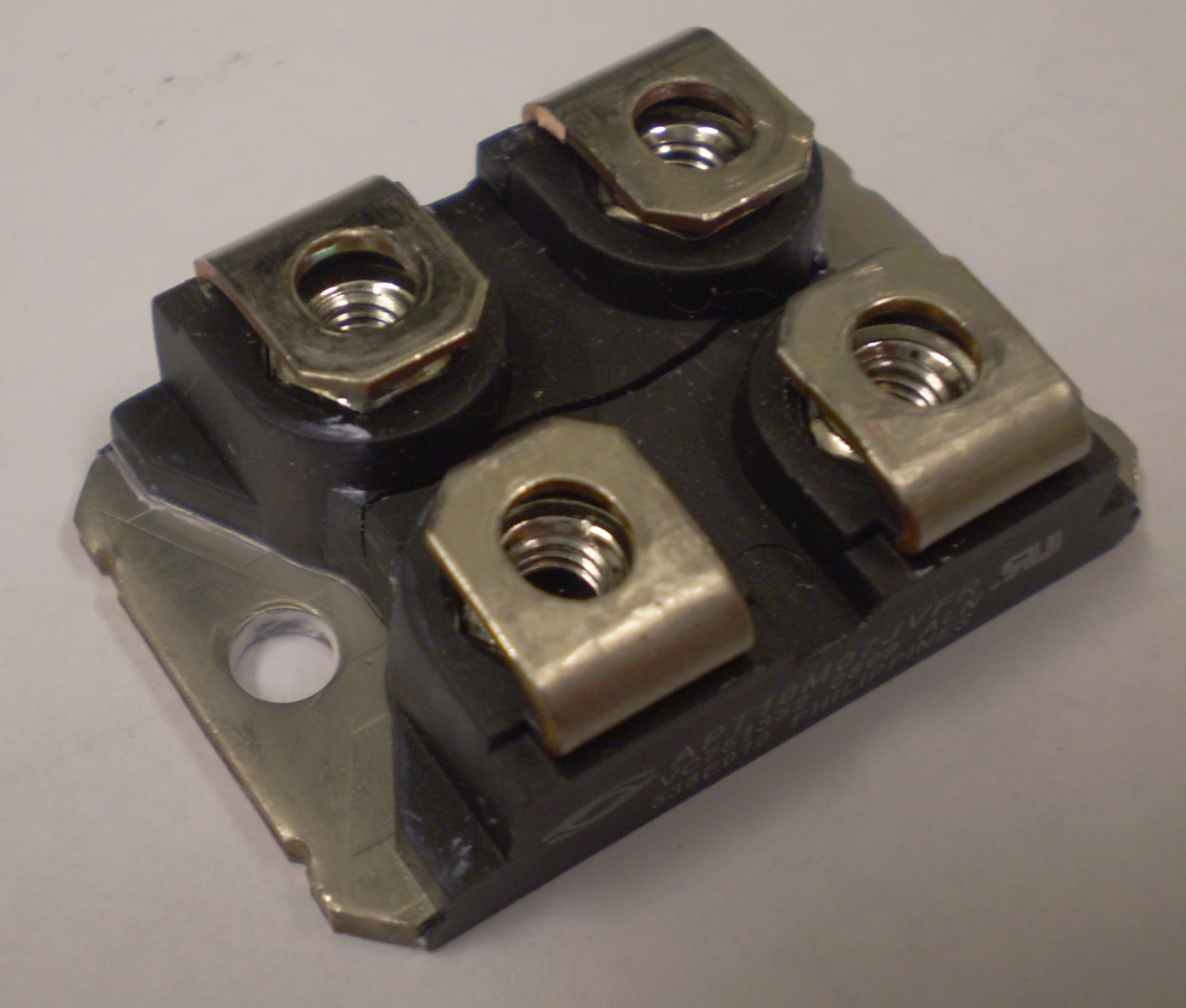
Click here to see what happens if you overheat a FET.
A lot ofcurrent flows through the CATS2. Improper grounding will burn out coils, the CATS2 and/or external equipment such as the ADWin controller! This is not a possibility, it is a probability! Ensure that the CATS2 and its power supplies are totally floating. The only ground can be through the analog inputs coming from the ADWin.
Connect all coils and supplies. Setup a waveform that ramps up to +7.75V (75A) in 100mS, holds it there for 750-1000mS then ramps back down to zero in 100mS. Use a length of 12AWG copper wire to measure current by removing two short pieces of insulation 18cm apart. Clip a voltmeter to these wire taps, read it as 1mV/A. Connecting the waveform to one channel at a time, measure the coil current for each channel. For the bipolar channels, both a +7.75V ramp and a -7.75V ramp must be done seperately. This calibration gives one point at the high end of the IV transfer curve. Set the waveform to +0.75V (5A) and repeat the process for a low end calibration point for each channel. Assume the channels are linear - which they are.
If the power supply voltage (treat the conglamorate as one supply) is set too low then the required coil current cannot be reached because the FETs will saturate. If the supply voltage is too high then the FETs will dissipate excessive power and may burn out. To determine the optimal power supply voltage, the minimum voltage drop across each FET must be measured. To do this, first setup the complete coil currents profiles. Set the power supply to approximately 15V. On the channel 1 (Push coil) FET, measure V ds (drain to source voltage). A DVM set to record minimum and maximum voltages will do this quite well. Run the complete cycle and record the minimum voltage. Note that V ds goes down as the coil current goes up. Repeat this for every FET, including each of the four FETs in the bridges. The optimal power supply voltage would be when the lowest recorded V ds is 1.5-2V. This is based on a R ds(on) of 10mOhm at 100A plus 0.5-1V extra.
To set the temperature at which the fan cuts in, run the MOT at 50A. In far less than a minute the heatsink will warm up
to 35-40°. Adjust the fan trimpot on the bipolar board until the fan starts. Turn off the current, allow
the heatsink to coll and check that the fans turns of by about 30°. Run current through the quadrapole coild
check that it turns on the fan too.
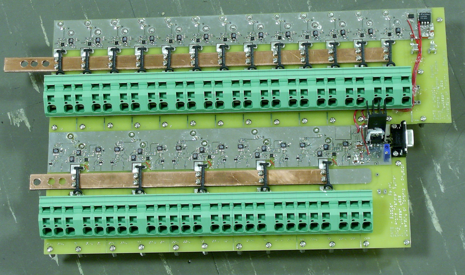
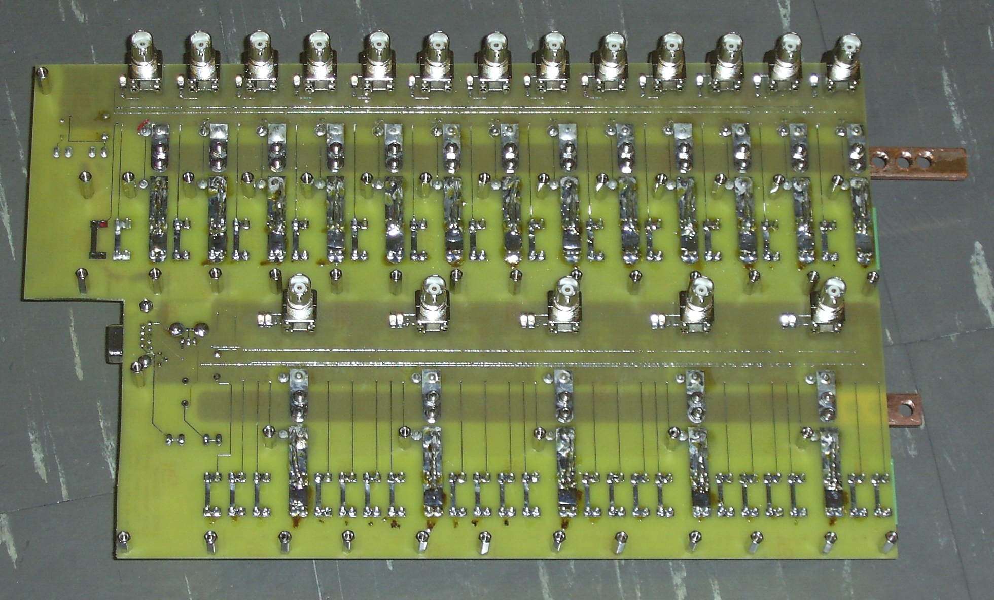
There are two power supplies: a small +24V supply to power the opamps and circuitry, and a large conglamorate capable of
150A. There are two PCBs: a huge combined board with the 13 unipolar and the 5 bipolar channels plus the
fan controls, and a small "Kitten" to monitor the supplies and control one current sink. All FETs are off the boards
on either heatsinks or the chassis. Those on the chassis cannot dissipate heat for mor than 100's of mS, those
on the heatsinks have forced air cooling and can run continiously. The heatsunk channels are for the MOT and the
Quadropole traps, plus the corner if required for setup and testing.
Each coil or coil pair has a fuse. As mentioned above, coils and FETs can burn (voice of experience) or be damaged if left with too much current for too long. ATC (Bussman) or ATO (Littlefuse) automotive style fuses are used due to their fast action but with ability to withstand short high overloads, as shown on the right. Failure of the software - by leaving a coil turned on at high current for too long - or a FET failure may cause high currents and a fuse to blow. LED idiot lights above each fuse indicate voltage to the coils, and blown fuses.
There are 13 unipolar channels. In the animation above, they are #1 through #12a and #16. Coils #1, #12a and #12b are single coils, all others are in series in anti-Helmholtz configuration (creates a magnetic null between them). Each channel is independantly capable of supplying from zero to 100A to its coil(s). Total current never exceeds approximately 150A. Each channel is typically on for much shorter than one second, following a roughly Gaussian shaped current profile. Channels overlap but never more than four are on at any instant.
As implied by "unipolar", these channels can supply current in only one direction through their coils. The analog input voltage controls the current, from 0A at +0.25V to 100A at +10V. Input voltages less than +0.25V will shut off the current, however inputs above +10V will continue to increase the current until the coil power supply limits by its voltage or current limits.
Power to each channel is supplied by a copper bar on the PCB. For each channel, a 2mOhm 5W current sense resistor (AKA Kelvin resistors) and an AD8212 high side current monitor provides approximately 10mV/A feedback. This is compared by an opamp to the analog input voltage and the source-follower power FET 's gate voltage is adjusted to maintain the coil current.
There are four bipolar channels. In the animation above, they are #13 through #16. All are single coils. Each channel is independantly capable of supplying from -100A to +100A to its coil. Total current never exceeds approximately 150A. Each channel is typically on for much shorter than one second, following a roughly Gaussian shaped current profile. Channels overlap but never more than four are on at any instant.
As implied by "bipolar", these channels can supply current in only both directions through their coils. The analog input voltage controls the current, from 0A at +0.25V to +100A at +10V for one polarity and from 0A at -0.25V to -100A at -10V. Input voltages between ±0.25V will shut off the current, however inputs above +10V or below -10V will continue to increase the current until the coil power supply limits by its voltage or current limits.
Power to each channel is supplied by a copper bar on the PCB. For each channel, a 2mOhm 5W current sense resistor (AKA Kelvin resistors) and an AD8212 high side current monitor provides approximately 10mV/A feedback. The feedback is shared by the positive and negative sub-channels. For the positive sub-channel, this feedback is compared by an opamp to the analog input voltage and the source-follower power N-FET 's gate voltage is adjusted to maintain the coil current. For the negative sub-channel, the analog input voltage is inverted but otherwise the circuit is the same. Therefore, when the analog input voltage is positive, the positive sub-channel sees both a positive control voltage and a positive feedback voltage (as with the unipolar channels); but when the analog input voltage is negative, the negative sub-channel will see both a positive control voltage and a positive feedback voltage.
The opamps have a single supply. In each bipolar channel, the two opamps cannot be active at the same time due to the inversion of their control voltages being complimentary (AKA inverted). At any instant, one or both opamps will be saturated at the negative rail (ground). The power section is a standard H-bridge with four N-FETs, either discrete or in a module. The high side is connected to the large power supply through its channel's current sense resistor, the low side is grounded, the coil is between the two source-drain junctions. The two opamps drive the upper FETs, making them source followers in the same fashion as the unipolar channels. Each lower FET has a pullup resistor to its gate to ensure full R ds(on) saturation. However, that alone would short the large power supply very effectively. Each opamp drives a BJT base via a resistor, such that the BJT saturates on when the opamp comes out of saturation and pulls down that low side FET's gate. In this way, as a high side FET is about to be turned on by its opamp, the low side FET below it is turned off by the same opamp. This method relies on the difference of the BJT's base threshold of +0.7V being lower than the FET's V gs(thresh) of >+2V to provide a dead band as the opamp slews up or down.
Coils 15 and 16 serve a dual purpose. They are the last stage of the transfer and also the experiment coils. During the transfer, they operate independantly, with 16 bipolar (pull and push the MOT) and 17 as unipolar (pull the MOT). During the experiment, they must have exactly the same current so that the MOT is in a known position. If they were operated independantly during the experiment, any drifts in either analog input voltages or component values would result in different coil currents and the magnetic null position would move. To solve this, the coils are wired in series with coil 16 connected to a unipolar channel and coil 15 connected to a bipolar channel.
Coils 15 and 16 go through a five step process. During most of the the MOT transfer before the MOT reaches coils 15, both coils are off. Refer to the diagram below. The Kitten daughter board control Q3, as a voltage controlled current sink.
Channel to Coil Mapping and Wiring Diagram
| Unipolar
Channel |
Maps to
Coil |
Bipolar
Channel |
Maps to
Coil |
|
||
| U1 | 16 (Q-Pole)* | B1 | 12B* | |||
| U2 | 12A* | B2 | 13 | |||
| U3 | 11 | B3 | 14 | |||
| U4 | 10 | B4 | 15 (Q-pole) | |||
| U5 | 9 | B5+
B5- |
1 (Push)
2 (MOT)* |
|||
| U6 | 8 | Notes:
1) * means heatsink 2) U12 is defective, do not use. 3) B5 serves two functions. 4) Coil 1 (push) current is the sum of U13 and B5+. |
||||
| U7 | 7 | |||||
| U8 | 6 | |||||
| U9 | 5 | |||||
| U10 | 4 | |||||
| U11 | 3 | |||||
| U12 | Defective
|
|||||
| U13 | 1 (Push) | |||||
| Kitten | 15/16 special | |||||
| Sorry, no more chance for asking direct questions, queries, broken links, problems, flak, slings, arrows, kudos, criticism, comments, brickbats, corrections or suggestions. |
|

|
