

|
 Alan Stummer
Research Lab Technologist |

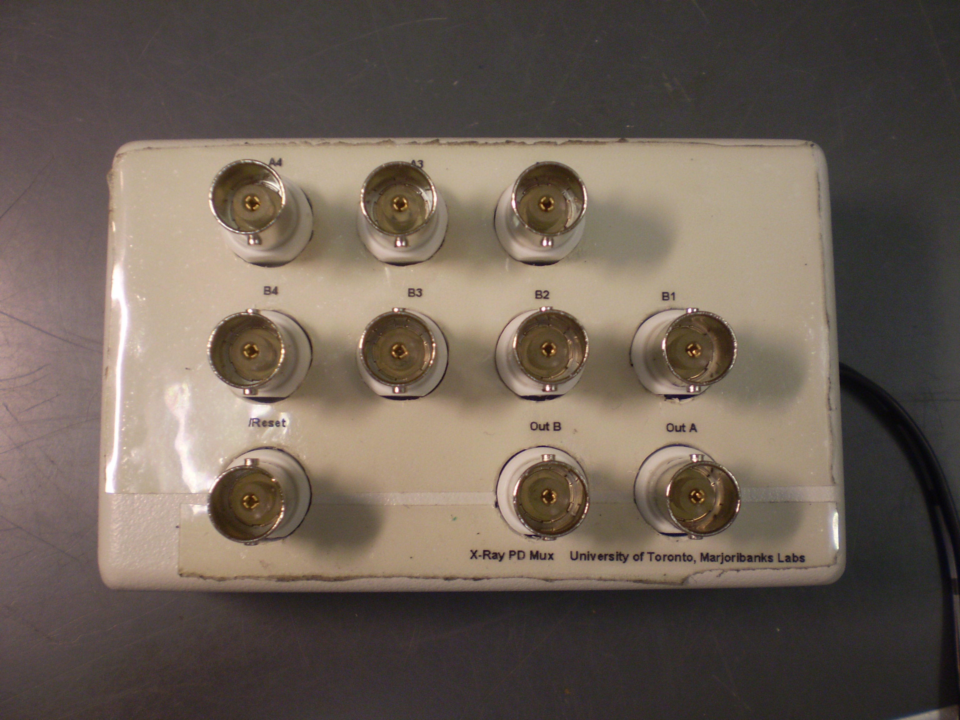
X-Ray PD Mux
|
Downloads
|
I am curious who uses what. Are these webpages a waste of time, or are they any help to others? Are the circuits, software and utilities appearing in other labs? Please send your comments or suggestions or what you have used (or not) or schematics of your version or pictures or anything! Email me, or be creative and send a postcard! I want to hear from the vacuum! |
Links
|
|
NOTICE: This webpage and associated files is provided for reference only. This is not a kit site! It is a collection of my work here at the University of Toronto in the Physics department. If you are considering using any schematics, designs, or anything else from here then be warned that you had better know something of what you are about to do. No design is guaranteed in any way, including workable schematic, board layout, HDL code, embedded software, user software, component selection, documentation, webpages, or anything. All that said, if it says here it works then for me it worked. To make the project work may have involved undocumented additions, changes, deletions, tweaks, tunings, alterations, modifications, adjustments, waving of a wand while wearing a pointy black hat, appeals to electron deities and just plain doing whatever it takes to make the project work. |
||

Started in June 2010 for Robin. Several X-ray PDs (photodiodes) are time multiplexed into an external digitizer. Specifically, two quad muxs (multiplexers) scan through their channels sequentially at 1uS per channel. Therefore, every channel is scanned every 4uS. The channels are labeled A2 to A4 and B1 to B4, where A1 has a fixed -4V to identify it. Note that channel A2 should be terminated if not used, so as to delimit the A1 framing channel.
Inputs - and therefore outputs - are limited to about ±4Vp. Do not exceed ±5Vp or damage may occur. Input to output resistance is approximately 130 Ohms to help prevent damage to the unit on high transient input voltages. Due to this protection resistance and the cable capacitance (it is not used as a transmission line), keep the cables from the unit to the 'scope as short as reasonable or the 'scope will have a significant rise time.
The input impedance of each channel is high. Unconnected inputs, although harmless, will drift to a voltage slightly negative to the previous channel's voltage. This is due to the inherent charge injection of the mux during switching.
An active low TTL input on the /Reset connector will hold the counter at channel 1 on the muxs, a TTL high or no connection will allow the muxs to scan. The reset input can be used to synchronize two or more units, although they will drift apart due to their plesiosynchronous nature.
A free-running 4MHz oscillator clocks a 4-bit synchronous counter. The two LSBs select the mux channel. All mux inputs and outputs have isolation resistors.
Return to homepage
| Sorry, no more chance for asking direct questions, queries, broken links, problems, flak, slings, arrows, kudos, criticism, comments, brickbats, corrections or suggestions. |
|

|