

|
 Alan Stummer
Research Lab Technologist |

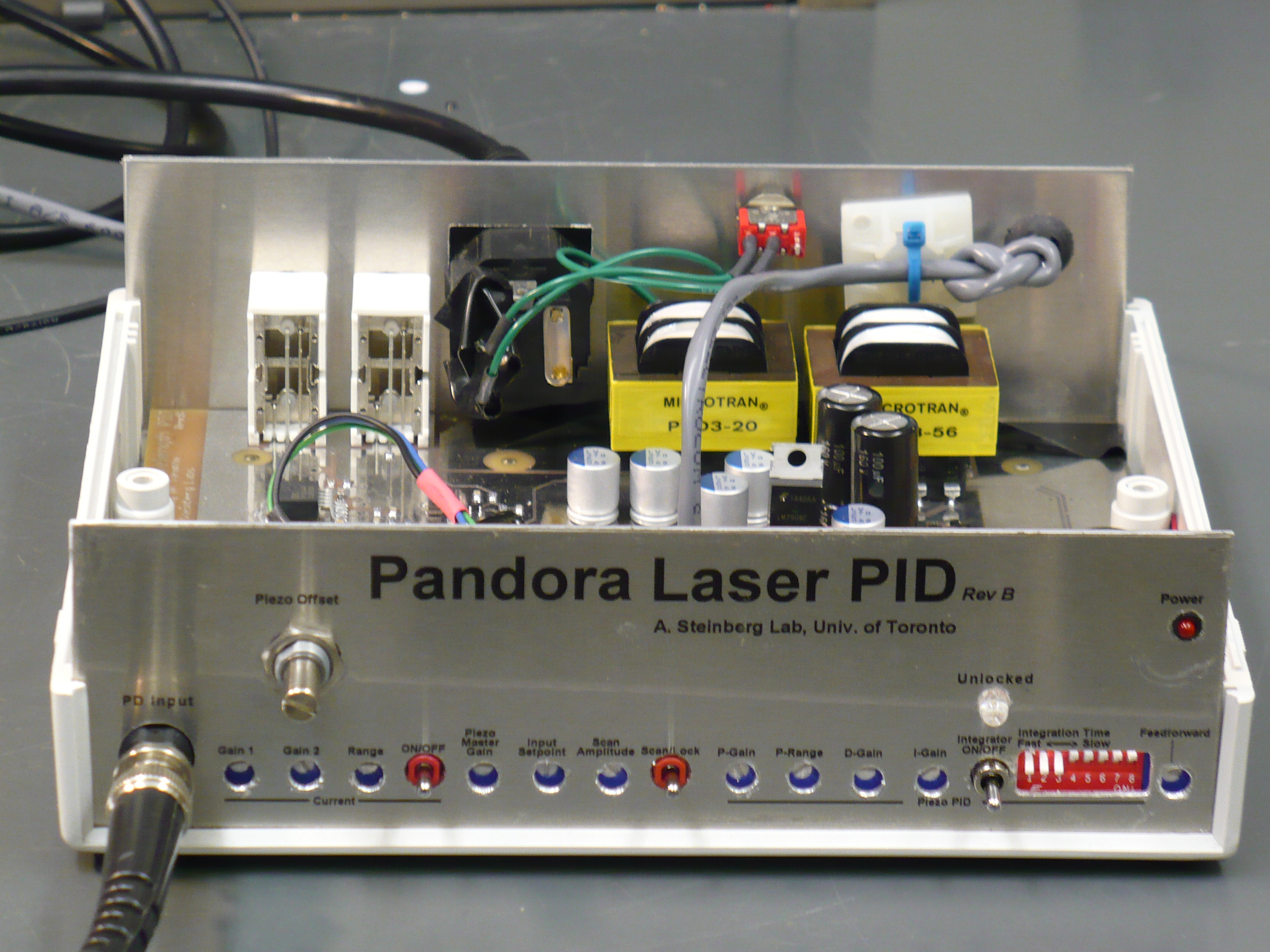
Pandora Wavelength PID
Downloads
|
I am curious who uses what. Are these webpages a waste of time, or are they any help to others? Are the circuits, software and utilities appearing in other labs? Please send your comments or suggestions or what you have used (or not) or schematics of your version or pictures or anything! Email me, or be creative and send a postcard! I want to hear from the vacuum! |
Links
|
|
NOTICE: This webpage and associated files is provided for reference only. This is not a kit site! It is a collection of my work here at the University of Toronto in the Physics department. If you are considering using any schematics, designs, or anything else from here then be warned that you had better know something of what you are about to do. No design is guaranteed in any way, including workable schematic, board layout, HDL code, embedded software, user software, component selection, documentation, webpages, or anything. All that said, if it says here it works then for me it worked. To make the project work may have involved undocumented additions, changes, deletions, tweaks, tunings, alterations, modifications, adjustments, waving of a wand while wearing a pointy black hat, appeals to electron deities and just plain doing whatever it takes to make the project work. |
||

Overview
Started in March 2011, for Aephraim's lab. This is a spin of a board made by Xingxing Xing which had grounding and other issues. It is merely an update of the existing circuit. The Balanced TIA project is the OE (Optical to Electrical) front end for this project. This project is very similar to the "Schlosser" Laser Lock made for the other half of Aephraim's lab a few years ago.
Pandora locks a laser to a transition line in a vapour cell. It has one photodiode (PD) input and two outputs: a 10MHZ bandwidth to tweak laser current and a 1KHz piezo for the external cavity.
Disclaimer
This is not my design. The circuit was given to me, I made only necessary changes to make it work but not necessarily to work as intended. I also laid out the PCB and packaged the project. No in depth analysis of noise, stability, drift, temperature sensitivity, mechanical clearances or any other parameters have been done by me but may have been done by the student. For information about this project please contact the student(s) or post-doc.
Pandora has a transimpedance amplifier (TIA) front end for the PD, with optional -12V bias on the BNC shield. Please don't short the cable to the table, although harmless it will remove the bias and kill the PD bandwidth. The TIA splits to an AC-coupled amplifier with proportional gain only for the laser's current modulation and a classic PID amplifier for the piezo.
| Control | Type | Description |
| Front Panel Connnectors | ||
| PD | BNC | Photodiode input |
| Current | BNC | Output to current modulation |
| Piezo | BNC | Output to piezo, 0 to +68V |
| Monitor | BNC | Scope Y-axis, from PD |
| Feed Forward | BNC | Piezo to current, anti-mode hop |
| Front Panel Controls | ||
| Current Gain 1 | Trimpot | First stage gain |
| Current Gain 2 | Trimpot | Second stage gain |
| Current range | Trimpot | Limits output range |
| Current On/Off | Switch | Enables current modulation |
| Crossing | Trimpot | Zero crossing point of PD |
| Piezo offset | Multi-turn pot | Piezo offset, AKA wavelength |
| Piezo Gain | Trimpot | Overall gain |
| Piezo P-gain | Trimpot | Proportional gain |
| Piezo I-gain | Trimpot | Integral gain |
| Piezo D-gain | Trimpot | Derivative gain |
| Piezo Integrator | Switch | Enables or zeros integral gain |
| FeedForward | Trimpot | Feedforward gain, piezo to current |
| Scan | Trimpot | Amplitude of scan |
| Internal Controls | ||
| Current Polarity | DIP switch | Inverts current output |
| Piezo Polarity | DIP switch | Inverts piezo output |
| Piezo Int Time | 8-DIP switch | Timing of integrator, large steps |
| FeedForward | DIPswitch | Inverts feed forward |
Return to homepage
| Sorry, no more chance for asking direct questions, queries, broken links, problems, flak, slings, arrows, kudos, criticism, comments, brickbats, corrections or suggestions. |
|

|