

|
 Alan Stummer
Research Lab Technologist |
|

|
ACync - AC Line Synchronizer |
|

Downloads
|
I am curious who uses what. Are these webpages a waste of time, or are they any help to others? Are the circuits, software and utilities appearing in other labs? Please send your comments or suggestions or what you have used (or not) or schematics of your version or pictures or anything! Email me, or be creative and send a postcard! I want to hear from the vacuum! |
Links
|
|
NOTICE: This webpage and associated files are provided for reference only. This is not a kit site! It is a collection of my work here at the University of Toronto in the Physics department. If you are considering using any schematics, designs, or anything else from here then be warned that you had better know something of what you are about to do. No design is guaranteed in any way, including workable schematic, board layout, HDL code, embedded software, user software, component selection, documentation, webpages, or anything. All that said, if it says here it works then for me it worked. To make the project work may have involved undocumented additions, changes, deletions, tweaks, tunings, alterations, modifications, adjustments, waving of a wand while wearing a pointy black hat, appeals to electron deities and just plain doing whatever it takes to make the project work. |
||

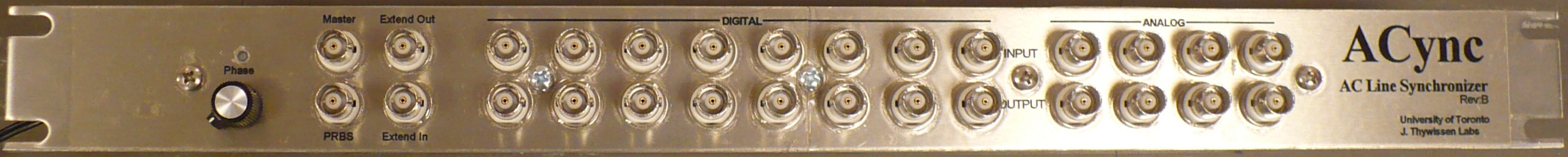
Started 2015 January for Stefan Trotzky in Joseph's lab. Eight digital and four analog signals are delayed and output synchronous to the local 60Hz AC line. This allows a repeatable ambient magnetic field for experiments. That said, the 50Hz or 60Hz AC line frequency/phase varies over time. Shifts heave been measured up to 90° over a minute, although the overall average frequency is held constant. The unit is a 1U 19-inch rack. All connectors are BNC.
The digital inputs and outputs (I/Os) are 5V TTL (inputs compatible with LVTTL) at 1uS resolution. The analog signals are compatible with [antiquated] ±10V 10mA drive, resolved to 12-bit (signed 11-bit, 10-bit ENOB) with 5uS resolution. A low frequency PRBS stream is provided for setup and monitoring. An Extend output and Extend input are provided for daisy chaining units, to ensure that they all use the same AC cycle and phase.
The Master (TTL) input determines how everything works. There are three modes.
- Passthrough As long as Master is low, all digital and analog signals are passed through from input to output.
- Freeze Immediately when Master goes high, all digital and analog outputs are frozen. This is maintained until the next desired AC line phase, probably zero-crossing. This mode lasts from 0mS to 16.67mS, dependant upon relative timing of Master and the AC line.
- Delayed The raison d'etre. Master is high and the AC line has passed the desired phase. All digital and analog inputs are repeated at their outputs but delayed by the Freeze time.
For proper operation, ensure that all analog and digital signals are stable before Master is set high. This will eliminate issues during the Freeze mode, being of indeterminate length. Similarly, ensure all outputs are stable before Master goes low.
To resynchronize over a longer time such as tens of seconds, hold all signals, put Master low then back high. It will resume on a known AC line phase.
The only control on the unit is a potentiometer to adjust the delay after the positive going zero-crossing of the AC line. This effectively sets the AC line phase for the Delayed mode to begin.
A PRBS output can be connected to any digital input (would also work on any analog input) to test phase alignment against the Master and the AC line zero-crossing output.
If more than one ACync unit is to be used, connect Master to the first unit only. Connect the first unit's Extend Out to the second unit's Extend In. For a third unit, either split the first unit's Extend Out to the second and third unit, or, connect the second Extend Out to the third Extend In, etc.
Each analog channel has a gain (AKA slope) and offset (AKA zero) calibration.
- Allow the unit 15 minutes to warm up and stabilize.
- Connect a DC power supply to analog CH1 input. Connect a voltmeter between CH1 input centre pin and the CH1 output centre pin. This measures the common mode voltage (difference between the input and output).
- Set the DC supply to near zero. Adjust the CH1 Offset trimpot for a difference of zero. Note that excessive gain errors may prevent zero calibration until the gain is adjusted.
- Set the DC supply to around +9V (90% full scale). Adjust the CH1 Gain trimpot for a difference of zero.
- Repeat the above two steps over and over until the error is <1mV.
- Test at a DC input of -9V, average any errors between -9V, 0V and +9V.
- Repeat for CH2 to CH4.
Parameters
| Parameter | Min | Typ | Max | Comments | ||||||
| Timing | ||||||||||
| AC frequency | 50Hz | 60Hz | ||||||||
| Phase shift, adjustable | 0 | 15.84mS | 342° of 60Hz | |||||||
| PRBS baud rate | 1KHz | |||||||||
| Analog Channels | ||||||||||
| Number of channels | 4 | |||||||||
| Input voltage range | -9.925V | +9.925V | ||||||||
| Absolute maximum input voltage range | -18V | +18V | Otherwise irreversible damage | |||||||
| Electrostatic Discharge | 3KV 1 | |||||||||
| Input resistance | 20K | Thevinin equavalent of 20K at +2V | ||||||||
| Resolution (effective) | 10mV | 16-bit, 15.2-bit ENOB | ||||||||
| Zero output offset | -1mV | +1mV |
|
|||||||
| DC common mode error | -2mV | +2mV | ||||||||
| Sample rate in Passthrough mode | 2.5uS | AKA propagation delay | ||||||||
| Sample rate in Delay mode | 5uS | |||||||||
| Bandwidth | 10KHz | Single pole filter | ||||||||
| Noise | 1.5mV | DC-100KHz | ||||||||
| Output resistance | 25mOhm | |||||||||
| Sustained output into 50 Ohm load | ±1.75V | ±2V | ±2.5V | Output current foldback protection | ||||||
| Transient output into 50 Ohm load | ±3.25V | Output current foldback protection | ||||||||
| Sustained output short circuit current | 15mA | Output current foldback protection | ||||||||
| Transient output short circuit current | 65mA | Output current foldback protection | ||||||||
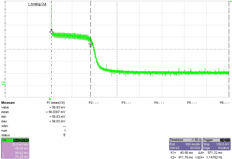
| Output short circuit transient time | 700mS | Before changing to sustained current 2 | ||||||||
| Single channel short circuit time | Indefinite | |||||||||
| Simultaneous sustained shorted outputs | 2 | |||||||||
| Digital Channels | ||||||||||
| Number of channels | 8 | |||||||||
| Input resistance | 100K | |||||||||
| Propagation delay in Passthrough mode | 50nS | |||||||||
| Sample rate in Delay mode | 1uS | |||||||||
| Input logic high level | +2.0V | |||||||||
| Input logic low level | +0.8V | |||||||||
| Absolute maximum input voltage | -0.5V | +6V | ||||||||
| Electrostatic Discharge | 2KV 1 | |||||||||
| Output logic high level | +2.5V | |||||||||
| Output logic low level | +0.4V | |||||||||
| Output resistance | 50 Ohm | |||||||||
| Output short circuit time | Indefinite | |||||||||
| Simultaneous sustained shorted outputs | 5 | |||||||||
| Notes | ||||||||||
| 1) Electrostatic Discharge (Human Body Model), per ANSI/ESDA/JEDEC JS-001 | ||||||||||
| 2) Sustained higher output currents will trip the current foldback protection. See the screen capture, across 1 Ohm load. | ||||||||||
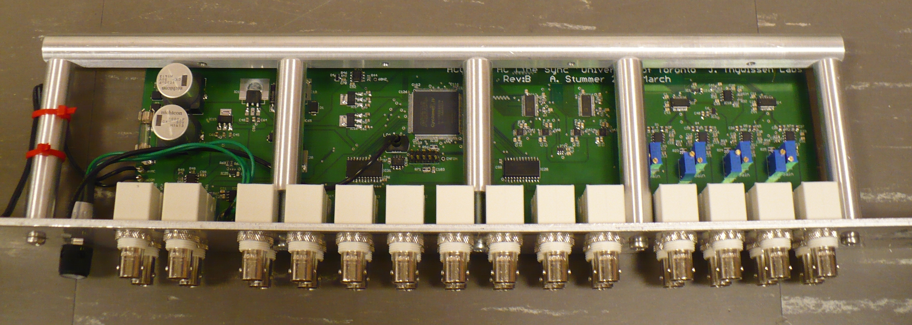
Not surprisingly, an AC transformer provides the AC reference. It also powers the unit. The heart of the unit is an Altera Cyclone IV FPGA running at a slow 60MHz. The digital I/Os are buffered for protection of the FPGA. Four serial ADCs provide the analog input streams, four serial DACs provide the delayed output streams.
The Extend In and Out are trinary level logic. They are not TTL compatible, Extend In will not be damaged by
TTL. The voltages are thirds of 3.3V: ~0.2V = Passthrough, ~1.6V = Freeze, ~3.2V = Delayed.
Return to homepage
| Sorry, no more chance for asking direct questions, queries, broken links, problems, flak, slings, arrows, kudos, criticism, comments, brickbats, corrections or suggestions. |
|

|