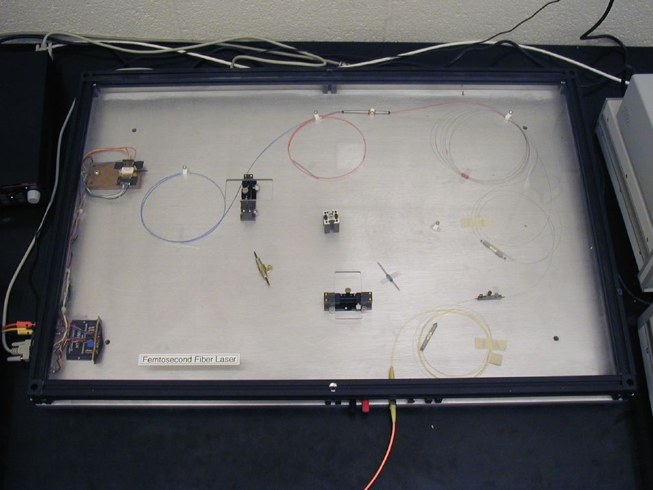
The laser consistes of a number of components, as described in the Primer, and many are also detailed below.
The whole laser is in a protective case. The polarization controllers can be adjusted, and these are the only moving parts. You must not reach inside the laser or attempt to open the case.
The system uses FC connectors, which screw on after a key in the fiber connector is located in a slot on the receiver. The ends of the fiber are glass and are easily damaged or scratched -- please use moderate care and close attention. These are PC types (physical contact) used here -- do NOT mix them or attempt to patch them together with other fibers which have a green boot. These have APC (angled physical contact. 8° angle on end of fiber ceramic) connectors which will damage the laser and hand-made fiber cables. Please use only fiber cables whith entirely flat ends, in black boots on yellow cables (SMF-28), or yellow boots on orange cables (MetroCor) .
Please see other cautions & warnings at the start of the Fiber Laser experimental page.
![]()
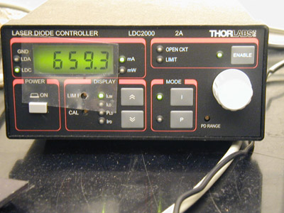
This provides precisely controlled power to the 980nm laser diode used to pump the fiber laser. It can be configured to display the current passed through the laser diode, up to a maximum value set only by laboratory staff. Do not alter this setting! Catastrophic damage to expensive components may result.
The card works by a sort of fluorescence: it must be 'charged up' by exposure to visible light (especially blue, and the fluorescent room lights are sufficient). This excitation does not readily decay until triggered by a low-energy 1550nm photon
Further notes for the curious: Probably the room-light excitation ends up in a metastable state, which cannot radiate by normal dipole coupling between upper and lower levels, because the excited and ground states have the same parity. The transition probability is found from their integral with the odd-parity dipole operator; the combination gives an odd-function integrand, which vanishes when integrated over all space.
The 1550nm photon has not much energy -- but it can drive the trapped excitation up to an opposite-parity state, which then can decay to ground by a dipole transition.
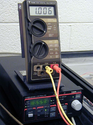
This monitors the temperature of the baseplate of the 980 nm
diode-laser pump for the fiber laser. It should never be much
different from 1.0 V. If it gives any other answer, turn off the
diode-laser controller (ENABLE button
OFF); then check that the 9V AC converter power supply at the
wall is still plugged in, and that the leads to the fiber laser
enclosure are intact. You must get Tak Sator or other staff technician
to confirm any changes or fixes you make, The pump laser can be
destroyed by overheating, or by quite small charges of static
electricity, from your hand to the electrical output connectors
of the fiber laser.. ![]()
This uses squeezing pressure applied to the fiber to induce stress-birefringence in the fiber.
The degree of birefringence is controlled by the small thumbscrew in the middle, pressing the glass fiber between two steel plates; only gentle pressure is needed, less than you can readily feel by your fingers, so this should not be screwed down with any force.
Pivoting or rolling the whole centre section around the axis of the fiber will permit you to orient the birefringence relative to the polarization state of the incoming light. Squeezing and pivoting, together, will let you make pretty much any polarization transformation you need.
Some technical information is available in these spec sheets from the manufacturer.
![]()
In the lab we're using a screw-on connector type identified as 'FC'. These FC connectors are the mechanical attachment mechanisms, but that is separated from how the fibers themselves couple together.
In one scheme, the fibers are polished flat across the end;
more commonly, they are polished on fine-grit polishing pads laid
over a rubber mat, which gives a radius to the surface: it is
convex. When two such cables are connected together, the optical
fibers at the very centre can be brought together until they touch,
and are sometimes held in place with slight spring-loading of
the mechanical connector. These are called physical contact,
or PC connections (below left).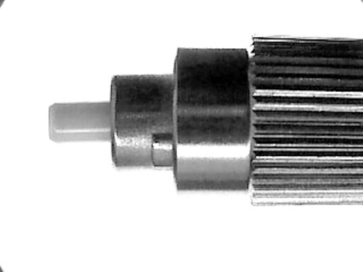
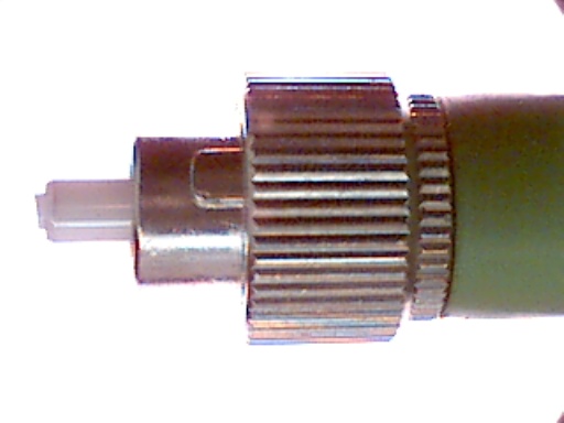
These perpendicular ends on the fiber can produce a reflection backwards down the fiber from whence the light came, and that can cause problems, especially in fiber lasers, which will amplify the feedback. In sensitive cases, then, the end of the fiber can be prepared with an 8° bevel on a central part of the ceramic holding the fiber centred (these match up fine, as the mating fiber is oriented by the keyed coupler-sleeve into which both screw. The small back-reflection is thereby launched back into the fiber at a 16° angle; you may know from the fiber optics experiments that light sent in at such a large launch angle will not couple well, and have large losses of energy as the light propagates. Thus these angled physical contact, or APC (above right), connections can exhibit much lower back-reflections.
It is very important not to attempt to couple these two types to each other -- certain damage will result which usually will destroy the fiber-optic cable, though it may be too subtle to feel as it happens. Likewise, it's good to be careful about screwing physical contact connectors together, avoiding unnecessary force. These cables are worth on the order of $100 each; numbers of them are hand-made for this lab, so it is an obligation of using the lab to please take care of the equipment.
The green plastic 'boot' or strain-relief of the cables indicates an APC scheme; in our lab black or yellow boots pretty usually indicate PC contact schemes.
Other mechanical connector schemes are available, some a simple plug-in scheme; these may house PC or APC contact schemes. A number of fibers available in the lab provide conversion bewteen one type and another. We sometimes use two such cables, designed to go from PC to APC, and then screw together the (compatible) APC ends, to make a cable with two PC contact scheme ends (be careful not to get confused, if you try this).
Technical (not required) note on cleaning fiber-connectors
![]()

This is a fiber-optic splitter: the input goes into COMMON, and Port1 and Port2 are outputs that share equally the signal put into COMMON.
Use it to take the laser output and split into two signals -- one for the optical spectrum analyzer, and one for the fast InGaAs detector attached to one TDS210 oscilloscope.
We have other splitters, and may in future use the fiber amplifier and another splitter to make multiple experimental channels.
![]()
Last revised: 7 April 2003 - rsm