
Alan Stummer, Research Lab Technologist

Danger - Potentially lethal voltages up to 1100V are present on this equipment and the MOT and Transfer coils!
Do not touch anything unless all four large power supplies are off and the Mag-O-Matic is unplugged for half an hour!
The large silver HV capacitors will hold a charge over 100V for up to 20 minutes.
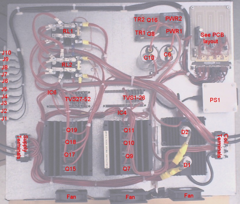
BEC Coil Driver, AKA "Mag-O-Matic"
|
I am curious who uses what. Are these webpages a waste of time, or are they any help to others? Are the circuits, software and utilities appearing in other labs? Please send your comments or suggestions or what you have used (or not) or schematics of your version or pictures or anything! Email me, or be creative and send a postcard! I want to hear from the vacuum! |
Downloads
Overview Charge Phase Steady State Phase Discharge Phase How to Connect to the Mag-O-Matic Description of Sequences Schematics Spice Simulation |
|
NOTICE: This webpage and associated files is provided for reference only. This is not a kit site! It is a collection of my work here at the University of Toronto in the Physics department. If you are considering using any schematics, designs, or anything else from here then be warned that you had better know something of what you are about to do. No design is guaranteed in any way, including workable schematic, board layout, HDL code, embedded software, user software, component selection, documentation, webpages, or anything. All that said, if it says here it works then for me it worked. To make the project work may have involved undocumented additions, changes, deletions, tweaks, tunings, alterations, modifications, adjustments, waving of a wand while wearing a pointy black hat, appeals to electron deities and just plain doing whatever it takes to make the project work. |
||

Overview
- drive up to 100A DC for five seconds out of ten, from supply of approximately 35-40V
- rise time (current from zero rated value) <500uS
- fall time (to <0.1% of steady state) <400uS
- current noise < 1:1e-4 (AKA -40dB) in 1Hz-1KHz band
- long term drift <<1% over minutes
- full control by AdWin sequencer
- total MOT coils 0.172 Ohms, 3.2mH in anti-Helmholtz configuration, switchable to Helmholtz, water cooled.
- total Transfer coils 0.148 Ohms, 2.3mH, always Helmholtz, reverseable polarity, water cooled.
Charge Phase
Because the resonant frequency is fixed by L and C, the only variable to determine the value of the coil current at 90° is the capacitor precharge voltage. This has to be adjusted empirically, it is not worth the trouble of automating this process.
The capacitor is charged by a 8.5W DC-DC converter. It is powered from +12V and generates up to 1KV. The converter is turned on after the end of the discharge phase and has several seconds to charge the capacitor. It is turned off just before the charge phase starts.
An oscilloscope screen capture is available of the MOT coil current rising from zero to 26.5A in 350uS.
Steady State Phase
Originally, HP HP6292B (40V, 50A) supplies were used with two in parallel for the MOT coils and one for the transfer coils. Disappointingly, these were found to drift over hours and have been replaced by Kepco ATE15-50M (15V, 50A) in the same configuration. Of the two MOT supplies, one is remotely controlled with the other slaved to it.
Discharge Phase (Flyback)
TVSs are similar to zener diodes. Above a certain voltage, they conduct. The difference is that TVSs can absorb lots of power for short amounts of time. The limitation is that the breakdown voltages are lower that what is required for this project. However, conveniently, TVSs can be stacked in series to increase the apparent breakdown voltage. Two parallel stacks of twelve TVSs in series limit the flyback voltage V to about 1KV. The TVS used is Micro Semiconductor's 15KP60A. Its breakdown voltage is nominally 70.4V, peak currents are 154A, rated peak power is 15KW (assuming an exponential decay with half power at 1mS or less), On resistance typically 0.18 Ohms. In this project with a peak design current of 100A, the peak power per TVS is a mere 8.8KW for <<1mS. At 100A, the actual voltage drop across each TVS will be 70V plus the IR drop of 18V (from 50A and 0.18 Ohms).
The switching device used is an IGBT (Insulated Gate Bipolar junction Transistor). This type of semiconductor is a cross between a conventional BJT (Bipolar Junction Transistor, AKA "transistor") and an enhancement mode MOSFET (Metal Oxide Shield Field Effect Transistor). Although retaining the worst of both worlds (poor saturation Vce-sat, high Miller capacitance Ccg and its other effects), they are capable of handling high power. The IGBTs used, International Rectifier's IRG4PSH71KD-ND, can work up to 1.2KV, 78A, 350W and 150°C. The 1.2KV determines V in the above equation and ultimately the time to collapse the magnetic field. The other parameters are not being pushed.
An oscilloscope screen capture is available of the MOT coil current falling from 60A to zero in 149uS.
How to Connect to the Mag-O-Matic
MOT Coil On: TTL input. Logic 1 will turn on the MOT coils by turning on the IGBTs. The two MOT power supplies will be connected to the MOT coils, they should be in CC (Constant Current) mode.
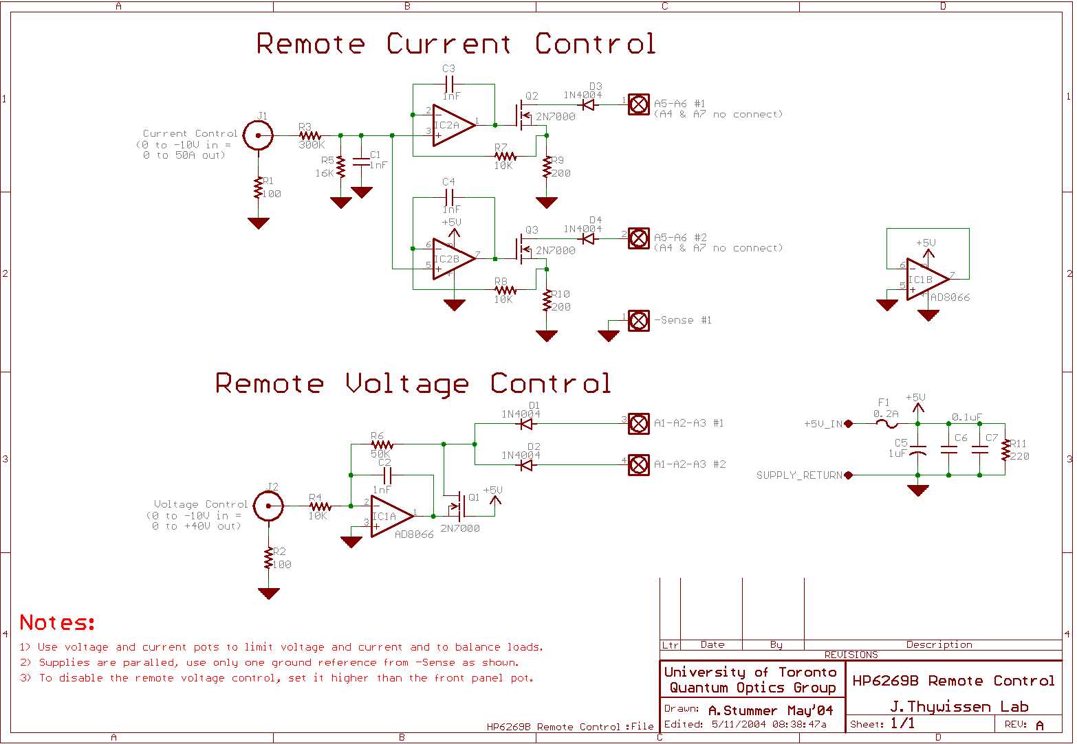
MOT Coil HV Set: Analog input, 0V - +10V into 15KΩ, default 0V. This voltage is multiplied 100 times to become the MOT high voltage ("HV") as described above in Charge Phase. The high voltage is set for critical damping of the rising current in the MOT coil. An empirically derived transfer curve relates MOT coil current and required MOT HV. The MOT HV capacitor must be precharged for >1 second before use (see next input, MOT Coil Fast On).
MOT Coil Fast On: TTL input. Pulsing this input high for 1-10mS will discharge the MOT HV capacitor into the MOT coil. The capacitor must be precharged for >1 second before use (see previous input, MOT Coil HV Set).
MOT Current Monitor: Analog output. Connect a meter or to a monitoring input such as an AdWin analog input. This output shows the measured MOT coil current with a scaling of +2.5V/50A (native scaling), or 20A/V. Bandwidth is 50-100KHz. Some noise from nearby wiring will be picked up, do not take this signal as gospel. For details of the device, see the Sypris NT-50 datasheet .
MOT HelmHoltz: TTL input. Logic 1 will change the MOT coils from anti-Helmholtz to Helmholtz configuration. WARNING MOT coil current must be completely off before changing the state of this input. This means that if the input is changed from either 1 to 0 or from 0 to 1 while any current is in the coils, the relays will arc and may be permanently damaged or cause inconsistent results in the future!
XFER Coil On: Same as MOT Coil On but applies to the Transfer coil.
XFER Coil HV Set: Same as MOT Coil HV Set but applies to the Transfer coil.
XFER Coil Fast On: Same as MOT Coil Fast On but applies to the Transfer coil.
XFER Current Monitor: Same as MOT Current Monitor but applies to the Transfer coil.
XFER Coil Reverse: TTL input, default logic 0. Logic 1 will reverse the polarity of the Transfer coils, used during transfer of the trapped atoms up to the chip. WARNING Transfer coil current must be completely off before changing the state of this input. This means that if the input is changed from either 1 to 0 or from 0 to 1 while any current is in the coils, the relays will arc and may be permanently damaged or cause inconsistent results in the future!
Fans Off: TTL input. Logic 1 will turn the IGBT cooling fans off. Because the fans are mechanical devices, they will take a few seconds to stop or restart. Turning off the fans reduces acoustic noise, which may affect mirrors and therefore laser mode widths. Do not turn the fans off more than necessary because they do serve a purpose: cooling the IGBTs.
Description of Sequences
Overview of use of Constant Current and Constant Voltage: Constant Current ("CC") means that the supply is putting out a constant amount of current and the voltage varies and adjust as required. Constant Voltage ("CV") means that the supply is putting out a steady voltage and the current is varying up and down with the load. CV is the most common use of power supplies, however, all BEC work requires CC (magnetic field strength is proportional to current only, not voltage). Therefore, ensure that all power supplies are in CC when trapping. The CC setting is controlled either locally or remotely as the independent setting. The CV setting is set empirically so that the supply will be just in CC mode. For example, if a CC load of 20A shows 10V on the voltmeter, remove the load and set the voltage to 10.5V or so. The amount that the voltage drops when changing to CC mode determines the damping and possible overshoot and droop of the load.Turning on and off the MOT coils - slow on, fast off: Use this simple sequence for simply turning on the MOT coils in <100mS. Set the MOT power supplies for the required constant current, set the voltage slightly above what is required when in CC. Apply logic 1 to MOT Coil On to turn the MOT coils on, apply logic 0 to turn the MOT coils off.
Turning on and off the MOT coils - fast on, fast off: Use this sequence to turn the MOT coils on as fast as possible. Set the MOT power supplies for the required constant current, set the voltage slightly above what is required when in CC. Apply the required voltage to MOT Coil HV Set to charge the MOT HV capacitor and allow at least one second for it to stabilize (longer is harmless). When ready to turn on the coils, reset the MOT Coil HV Set to 0V, within 100mS apply logic 1 to MOT Coil On then immediately apply logic 1 to MOT Coil Fast On for 1-10mS (longer is harmless).
To turn off the coils, simply apply logic 0 to MOT Coil On. MOT Coil Fast On should already be at logic 0.
Decreasing MOT coil current to non-zero value: Simply turn down the CC setting on the two MOT power supplies. The current will track the supplies.
Increasing MOT coil current from non-zero value: Set the two MOT power supplies to the new CC setting. If nothing else is done, the current will rise in <100mS to the new value. If a fast rise to the new value is required, follow the sequence above for turning on the MOT coils fast.
Turning the Transfer coils on, off or changing current: The Transfer coils follow exactly the same sequences as the MOT coils. The two sets of coils, MOT and Transfer, are independent and so can turn on or off or change without affecting each other.
Changing MOT coils between anti-Helmholtz and Helmholtz: As described in the connection descriptions above, the direction of current in one of the MOT coils can be reversed. Apply logic 0 or no connection for anti-Helmholtz, apply logic 1 for Helmholtz. WARNING MOT coil current must be completely off before changing the state of this input. This means that if the input is changed from either 1 to 0 or from 0 to 1 while any current is in the coils, the relays will arc and may be permanently damaged or cause inconsistent results in the future!
Changing Transfer coils polarity: As described in the connection descriptions above, the direction of current in the Transfer coils can be reversed. WARNING Transfer coil current must be completely off before changing the state of this input. This means that if the input is changed from either 1 to 0 or from 0 to 1 while any current is in the coils, the relays will arc and may be permanently damaged or cause inconsistent results in the future!
Transferring the trapped atoms to the chip: With the atoms held by the MOT and the Transfer coils on, smoothly and slowly reduce Transfer coil current by ramping the power supplies' constant voltage (CV) setting to zero. Reverse the Transfer coil direction and set the Transfer coil CC setting to its new setting. Ramp up the CV until the supplies are in CC. Note that the use of CV will ensure that the supply voltage drops below the diode forward voltage, ensuring zero current. If CC was used, any zero offsets would allow an albeit low but non-zero current by supplying enough voltage to forward bias the diodes. As the load is largely resistive and therefore linear, dI will track dV but with an offset zero. With such low dV, the effects of the coils inductance can be ignored.
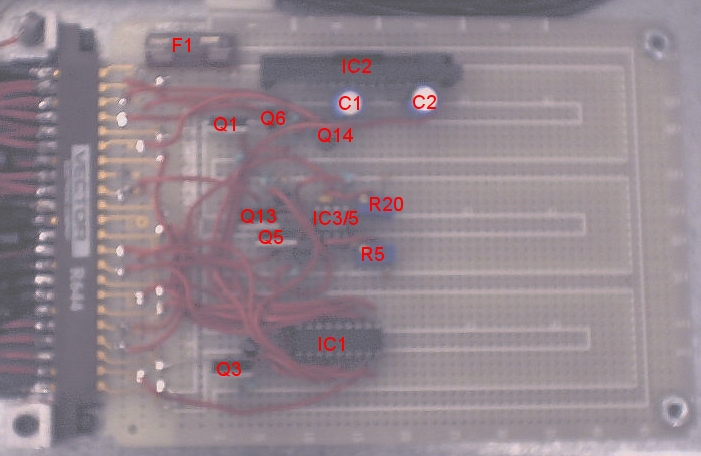
Schematics
The schematics are done in Eagle schematic capture program. Right click and save the schematic then open it with Eagle. There is also a schematic for the AdWin to remotely control the two pairs of HP6269B power supplies, although this model of supply is no longer used.Spice Simulation
This charge - steady state - discharge cycle was simulated in Spice, using the 5Spice variant. It appears to be accurate once the inductance value was corrected. Impressively, Spice even predicted the harmless LC resonance at the end of the discharge phase. Liberties were taken with the circuit to simulate the start of the discharge phase at 1mS by the addition of a switch. The latest and hopefully accurate Spice schematic file, Spice analysis file.Return to homepage
| Sorry, no more chance for asking direct questions, queries, broken links, problems, flak, slings, arrows, kudos, criticism, comments, brickbats, corrections or suggestions. |
|

|