
Alan Stummer, Research Lab Technologist
BEC Coil Driver, AKA "Mag-O-Matic2"
|
Downloads
Overview Steady State Phase Discharge Phase Charge Phase How to Connect to the Mag-O-Matic2 Description of Sequences Spice Simulation |
|
|
NOTICE: This webpage and associated files is provided for reference only. This is not a kit site! It is a collection of my work here at the University of Toronto in the Physics department. If you are considering using any schematics, designs, or anything else from here then be warned that you had better know something of what you are about to do. No design is guaranteed in any way, including workable schematic, board layout, HDL code, embedded software, user software, component selection, documentation, webpages, or anything. All that said, if it says here it works then for me it worked. To make the project work may have involved undocumented additions, changes, deletions, tweaks, tunings, alterations, modifications, adjustments, waving of a wand while wearing a pointy black hat, appeals to electron deities and just plain doing whatever it takes to make the project work. |
|
- Full list of files (always up to date).
- Coil driver schematic (Eagle).
- Schematic in PDF (may be out of date)
Overview
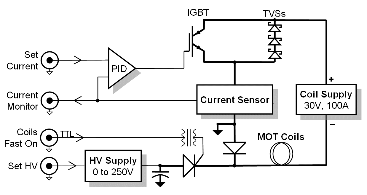
For use in Joseph's second lab, original contact is Mike Yee, project started July 2007. This project is based on the original Mag-O-Matic, except that A) it has only one channel, B) it is CC rather than just a switch, and D) the MOT coils are permanently in anti-Helmholtz.. The coil driver circuit controls the coils which generate the magnetic fields for the MOT coils. This project is a test bed for constant current (CC) driving of the MOT coils. Current is measured with a hall effect sensor device and compared to a set value. Normally this would be mundane but the load is inductive so loop stability depends on control phase shifting. Once this system is worked out, it will be repeated several times for the transfer coil setup as part of the larger lattice experiment.
Basic Mag-O-Matic2 parameters include:- drive up to 100A DC for up to 5 seconds out of 10 (worst case). Typical trapping is at 42A for 5 out of 10 seconds.
- rise time (current from zero rated value) <100µS
- fall time (to <0.1% of steady state) <100µS
- current noise < 1:1e-4 (AKA -40dB) in 1Hz-1KHz band
- long term drift <<0.1% over minutes
- full control by AdWin sequencer
- total coils 0.38 Ohms, 240µH in anti-Helmholtz configuration with water cooled jacket.
Steady State Phase
For the record, four FETs were originally used but replaced by a single IGBT. First and least, the IGBT is cheaper. Second and important, the FET selected - International Rectifier's IRFBA90N20D - has a positive coefficient of drain current with temperature that can cause thermal runaway of one device. The APT200GN60J IGBT has a negative coefficient of collector current with temperature, although it is moot as there is only one IGBT.ss
Discharge Phase (Flyback)
TVSs are similar to zener diodes. Above a certain voltage, they conduct. The difference is that TVSs can absorb lots of power for short amounts of time. The limitation is that the breakdown voltages are lower that what is required for this project. However, conveniently, TVSs can be stacked in series to increase the apparent breakdown voltage. The TVS used is Micro Semiconductor's 15KP60A. Its breakdown voltage is nominally 70.4V, peak currents are 154A, rated peak power is 15KW (assuming an exponential decay with half power at 1mS or less), On resistance typically 0.18 Ohms. In this project with a peak design current of 100A, the peak power per TVS is a mere 8.8KW for <<1mS. At 100A, the actual voltage drop across each TVS will be 70V plus the IR drop of 18V (from 50A and 0.18 Ohms).
Charge Phase
Because the resonant frequency is fixed by L and C, the only variable to determine the value of the coil current at 90° is the capacitor precharge voltage. This has to be adjusted empirically, it is not worth the trouble of automating this process.
The capacitor is charged by DC-DC converter powered from +12V. The converter is turned on after the end of the discharge phase and has several seconds to charge the capacitor. It is turned off just before the charge phase starts.
How to Connect to the Mag-O-Matic2
Coil Set Current: Analog input, 0V to +2.5V representing 0A to 100A, therefore 40A/V. Below 0V shuts off the current fast and sets the big supplies to a higher voltage. Alternatively, set the large power supply in CC mode and set this setpoint from 0V to +2.5V and let the large power supply regulate the current.
Coil HV Set: Analog input, 0V to +10V into 15KΩ, default 0V. This voltage is multiplied 20 times (TBD) to become the high voltage ("HV") as described above in Charge Phase. The high voltage is set for critical damping of the rising current in the coil. An empirically derived transfer curve relates coil current and required HV. The HV capacitor must be precharged for >1 second before use (see next input, Coil Fast On).
Coil Fast On: TTL input. Pulsing this input high for 1-10mS will discharge the HV capacitor into the coils. The capacitor must be precharged for >1 second before use (see previous input, Coil HV Set).
Description of Sequences
Turning on and off the coils - slow on, fast off: Use this simple sequence for simply turning on the coils in <10mS. Simply put the Set Current for the required constant current.Turning on and off the coils - fast on, fast off: Use this sequence to turn the coils on as fast as possible. Apply the required voltage to Coil HV Set to charge the HV capacitor and allow at least one second for it to stabilize (longer is harmless). When ready to turn on the coils, reset the Coil HV Set to 0V, within 100mS apply the Set Current then immediately apply logic 1 to Coil Fast On for 1-10mS (longer is harmless).
To turn off the coils, simply set the Set Current to 0V or slightly below zero. Coil Fast On should already be at logic 0.
Decreasing coil current to non-zero value: Simply set the Set Current input.
Increasing coil current from non-zero value: Simply set the Set Current input. If nothing else is done, the current will rise in <10mS to the new value. If a fast rise to the new value is required, follow the sequence above for turning on the coils fast.
Spice Simulation
This charge - steady state - discharge cycle was simulated in Spice, using the 5Spice variant. It appears to be accurate once the inductance value was corrected. Impressively, Spice even predicted the harmless LC resonance at the end of the discharge phase. Liberties were taken with the circuit to simulate the start of the discharge phase at 1mS by the addition of a switch. The latest and hopefully accurate Spice schematic file, Spice analysis file.Return to homepage
| Sorry, no more chance for asking direct questions, queries, broken links, problems, flak, slings, arrows, kudos, criticism, comments, brickbats, corrections or suggestions. |
|

|