

|
 Alan Stummer
Research Lab Technologist |

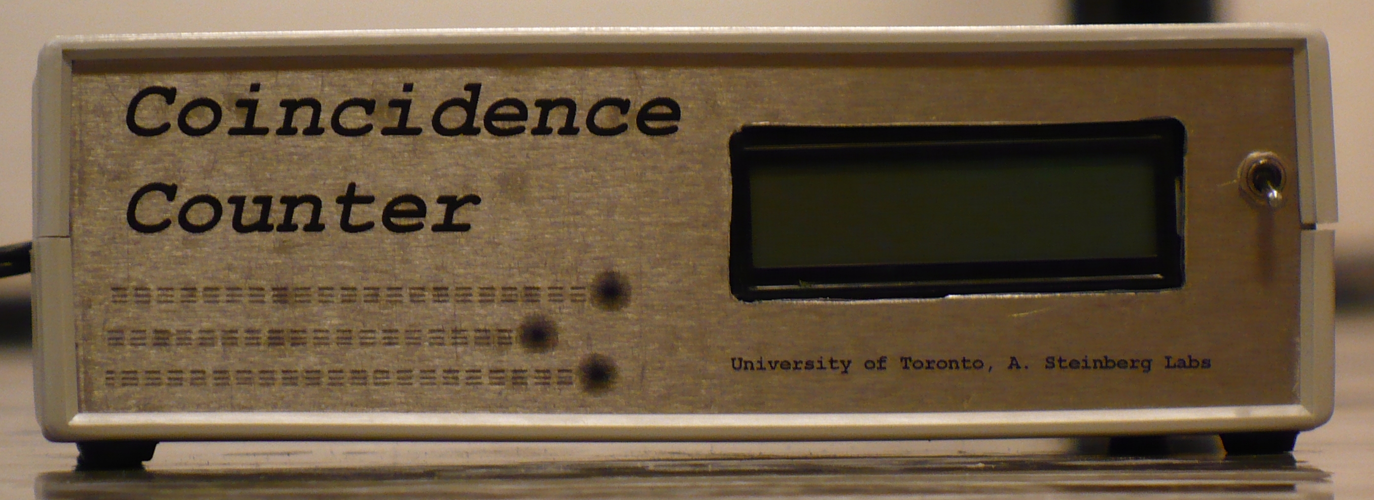
Coincidence Counter
Downloads
|
I am curious who uses what. Are these webpages a waste of time, or are they any help to others? Are the circuits, software and utilities appearing in other labs? Please send your comments or suggestions or what you have used (or not) or schematics of your version or pictures or anything! Email me, or be creative and send a postcard! I want to hear from the vacuum! |
Links
Overview How It Works Calibration Components A Note On The APDs Specs |
Latest Updates
|
|
NOTICE: This webpage and associated files is provided for reference only. This is not a kit site! It is a collection of my work here at the University of Toronto in the Physics department. If you are considering using any schematics, designs, or anything else from here then be warned that you had better know something of what you are about to do. No design is guaranteed in any way, including workable schematic, board layout, HDL code, embedded software, user software, component selection, documentation, webpages, or anything. All that said, if it says here it works then for me it worked. To make the project work may have involved undocumented additions, changes, deletions, tweaks, tunings, alterations, modifications, adjustments, waving of a wand while wearing a pointy black hat, appeals to electron deities and just plain doing whatever it takes to make the project work. |
|||

|
|
|
Overview
The detection is based on delay lines. An example is shown in the diagram on the right. A, B and C are three of the possible eleven APDs. A (trips at t 0 )is delayed a few nS by t d and appears as A'. Same happens with B/ B' and C/ C'. All three APDs fire, but at different times. A' is the first delayed signal to occur (at t 1 ) so that becomes the sample point. At t 1 , APDs A and B have fired, but C was too late. Therefore, the coincidence is recorded as both A and B only. No other coincidences can be recorded until all APDs are reset (they self-reset in 15-50nS, depending on model) at t 2 . A detailed timing diagram for the FPGA is available (in Word, requires the Timing font.to be installed - just copy to the /fonts/ dir), or as a .gif image.
Another way to look at it is simply that after the first delayed APD is detected, all non-delayed APDs are examined and that is the coincidence status.
The coincidence detection and counting is done in the FPGA. When requested by the host, the Rabbit halts the detection of coincidences (AKA pauses running), reads the counters from the FPGA , forms them into 1 to 8 (quantity requested by host) IP packets of 1026 bytes, sends them to the host via UDP then restarts coincidence detection (AKA run). Coincidences are first bit-mapped into words. For example, if A and C APDs fire, they carry binary weights of A = 2 0 and C = 2 2 resulting in a coincidence word of 1 + 4 = 5. There are 2 11 - 1 or 2048 possible coincidence words, or combinations. There are 2048 counters, each one representing a particular APD coincidence. Note that counter 0 is not a coincidence, but it is the total of all counters, to be used for rate calculations. The counters are 32-bit, so can count up to 2 32 - 1 or 4,294,967,295. Due to IP packet size limitations, only 256 counters can be sent to the host per packet. The first packet contains full coincidence reporting for the first eight APDs, the first two packets cover nine APDs, the first four packets cover 10 APDs and the full eight packets cover all 11 APDs.Two calibrations have to be made: channel to channel timing and per channel delay.
Per Channel Delay Calibration: This is a one-time calibration to determine the transfer curve between the set delays and the measured delays. The simplest method is with a fast oscilloscope, >=500MHz. Put the two scope probes in the two calibration points for channel #1, being sure to use proper short high speed grounds for the probes. Ensure that a pulse train, either from the experiment or from a signal generator, is going into channel #1. Record the time difference between the two 'scope channels for various set time delays. Repeat for the other 10 channels.
Channel to Channel Timing Calibration : This calibration adjusts for the timing differences between the channels and must be done every time the experiment changes. Although the channel to channel error inside the unit may be several nS, this will be swamped by the external delays caused by different optical and electrical path lengths. To calibrate, setup the experiment completely so that coincidences occur. Because channel to channel timing is relative, use channel #1 as the reference. For simplicity, cover all APDs except for channels #1 and #2. Set the delays to maximum (255nS), coincidences should be recorded by the Coincidence Counter. Reduce the timing window until the coincidences stop. Adjust channel #2 cable longer or shorter until coincidences occur. Shorten the timing window again, adjust channel #2 cable again to get coincidences. Repeat this process until the timing window is as as short as possible. Repeat with all other channels one at a time.
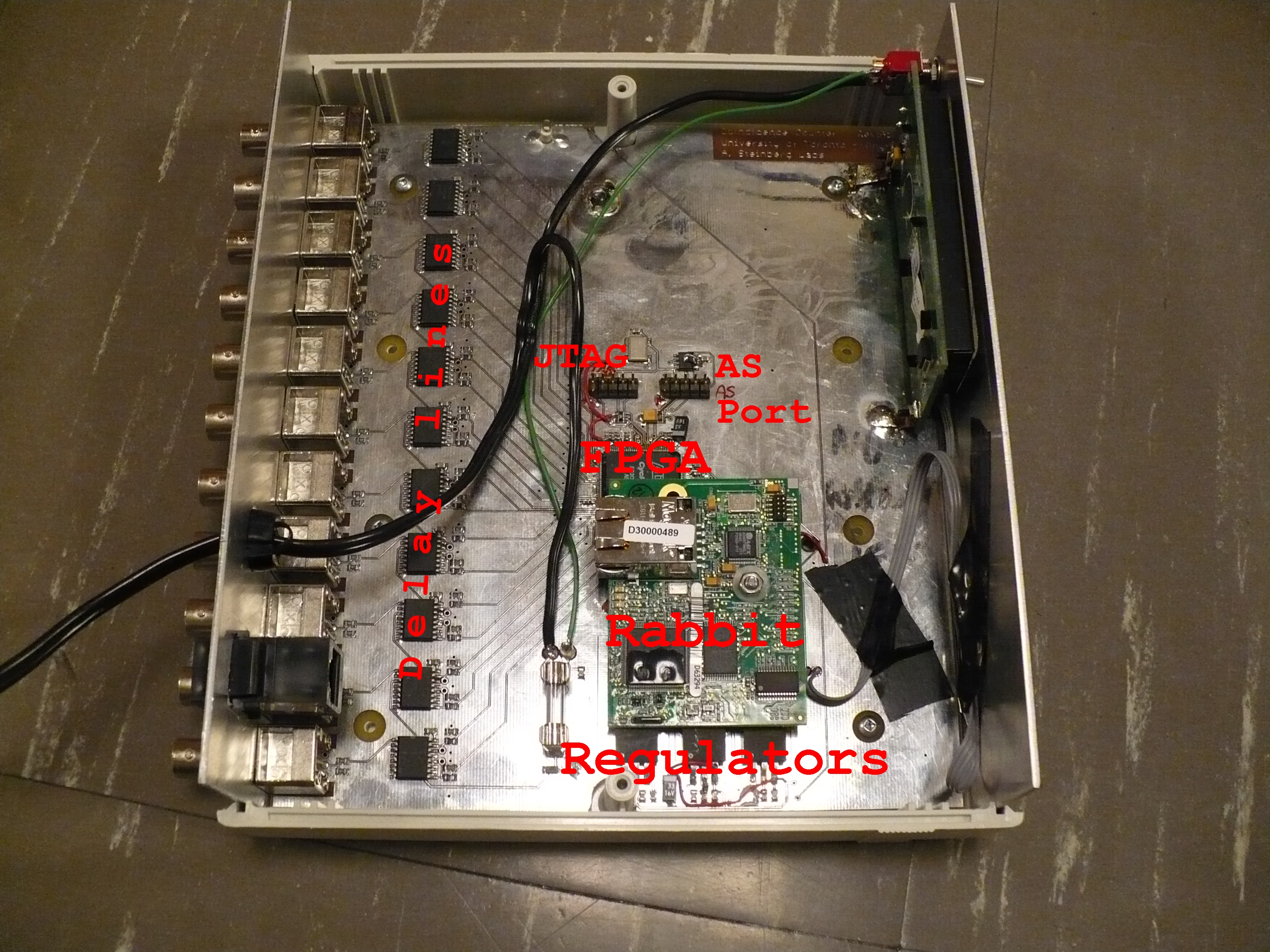
The core of the coincidence detection is based around one Maxim DS1023 programmable timing element per channel. This delay line has two outputs: a reference which is delayed a fixed amount from the input, and a delayed output which is delayed from the reference output by a programmable period. See the tests of 1nS steps and of 10nS steps .
All 22 outputs from the 11 delay lines are sent to an Altera Cyclone III FPGA, where the coincidence detection is performed. An array of 2 11 counters keeps track of all permutations of coincidences from the 11 APDs (only one APD firing without any others is recorded as a "single" but is inherently not a coincidence). The FPGA code is written in System Verilog using Quartus II .
Control and data retrieval from the FPGA plus UDP/IP communications with the host computer is performed by a Rabbit Semiconductor RCM4200 module. The Rabbit code is written in Dynamic-C.
Software on the host computer is not my problem! ..except for a test GUI.
There are two generations of APDs. The "APD Classic" has a ~50nS output pulse with a ~50nS recovery time and is able to drive TTL levels into 50 Ohms, which was good for transmission lines. The new and improved APDs have ~20nS output pulses with ~20nS recovery times but have weaker outputs, capable of driving TTL levels into 70 Ohms or more. The APD inputs have been changed to accomodate the newer weaker signals.
| Parameter | Conditions | Min | Typ | Max |
| Coincidence window range | 0nS | 255nS | ||
| Coincidence window adjustment step size | 1nS | |||
| Channel to channel deviation | See note 1. | -8nS | ±2nS | +8nS |
| APD input pulse width | See note 2. | 20nS | ||
| APD input voltage | See note 3. | 3.5V | 5V | 5.5V |
| Input load impedance | 45 Ohms | 50 Ohms | 55 Ohms | |
| Coincidence counter limit | See note 4. | 4,294,967,295 (2 32 - 1) | ||
| Coincidence counter array retrieval by UDP/IP | See note 5. | 240mS | 250mS | |
Notes:
|
||||
Return to homepage
| Sorry, no more chance for asking direct questions, queries, broken links, problems, flak, slings, arrows, kudos, criticism, comments, brickbats, corrections or suggestions. |
|

|