PHY405 Electronics, Lab 6
Adapted from Prof. David Bailey's website in 2022
Overview
- Controlling and measuring currents
- Photodiodes
- Communication via light
Please read this whole write-up before starting; knowing what comes later may help earlier.
- e.g. It is easier to do the later exercises if you lay out the first two op amp circuits on the breadboard so that the LED and photodiode can easily be pointed towards each other.
Safety Reminders (for both humans and electronics)
You can easily destroy a MOSFET by zapping its pins with even small static shocks.
Be sure discharge yourself before picking up a MOSFET; avoid touching the metal pins.
Before powering the circuit, double check the 2N7000 specifications to be sure the pins are correctly connected.
Arduino analog pins are electronically fragile and can fail in ways that are not immediately obvious.
Be careful to keep unused leads away from the Arduino If an unused lead with an exposed pin accidentally grazes the Arduino board, it could short out and possibly damage the Arduino.
Exercises
You will be asked for photos of some of your circuits.
- You will lose points if your hook-up wire colours do not follow a clearly specified sensible convention, e.g. as described in the previous lab.
Low-Power Op Amp
Today you’ll be using a MCP6004 Quad Op Amp. This chip contains 4 low-power, low-voltage op amps that are powered by 1.8 to 6VDC. This is good choice for battery or Arduino powered applications.
- If you apply more than 6 volts you will fry this op amp!
- The op amps will be powered with +5V from your Arduino.
- Do not use the EDU36311A DC power supply* at all today.
- Power for all 4 MCP6004 op amps are supplied on pins 4 (+ve) and 11 (-ve)
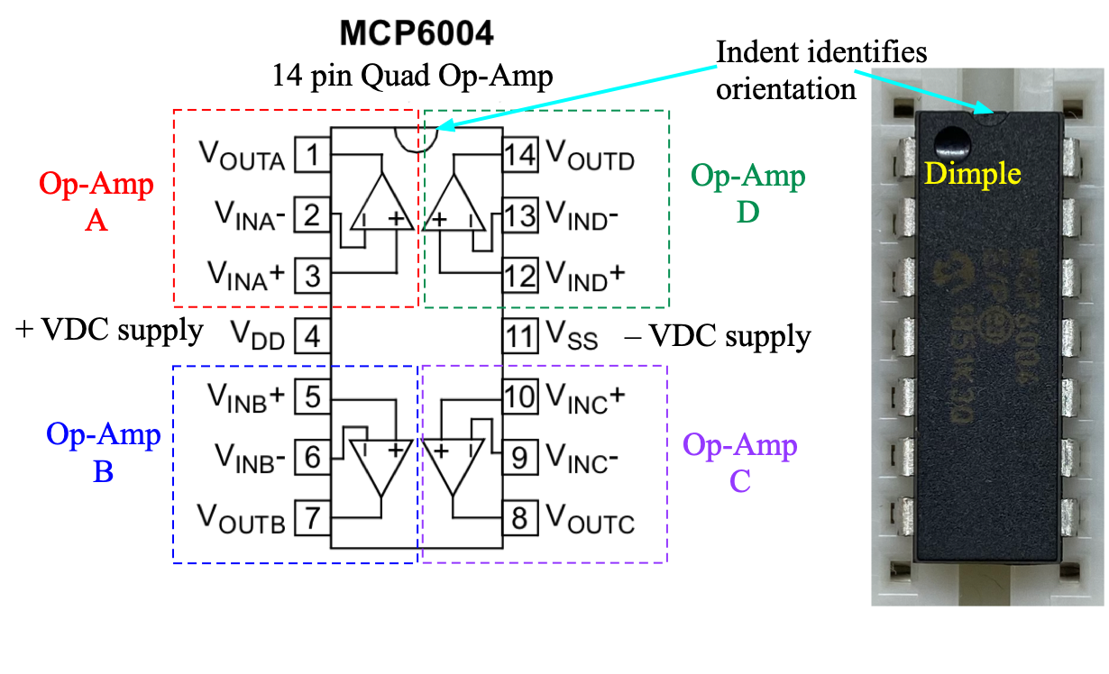
MCP6004 Quad Op Amp pin assignments from its datasheet
Voltage Controlled Current Source (Transadmittance Amplifier)
- Admittance is 1/impedance.
- Transadmittance (“transfer admittance”) is the ratio of a circuit’s output current to input voltage.
The optical power emitted by a light-emitting diode (LED) is proportional to the current through it. Most power supplies deliver known voltages, and the current through a circuit depends on its (often hard to calculate and frequency dependent) impedance. The current through a diode is a very non-linear function of applied voltage, so it would be nice to directly control the current. One way to do this is with a Voltage-Controlled Current Source (VCCS) that uses an op-amp and a MOSFET. Such current sources are useful whenever current is the primary parameter of interest, e.g. LEDs or generating magnetic fields.
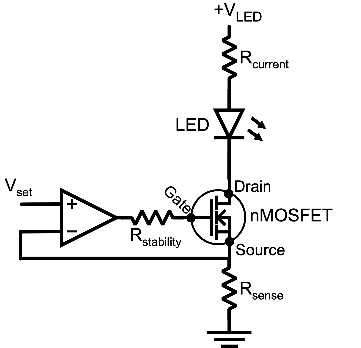
A voltage-controlled current source (VCCS) using an op-amp and an nMOSFET transistor to drive a current through an LED load. The optional series resistor,
This exercise will only be looking at positive voltages, so you should set up positive power rails supplied by the Arduino 5V pin and ground rails connected to a Arduino ground (GND) pin.
- The op amp +VDC pin 4 (
- Be careful not to get these connections backwards!
Because the LED current is controlled, any voltage significantly above the LED’s threshold should be fine, so we can choose the LED supply voltage
- For example, for your project you might build a standalone Arduino controlled circuit, where the Arduino is powered by a 9V battery, and the Arduino provides +5V to the circuit.
We will power the circuit from the Arduino
- Confirm that the voltage from the Arduino is about
- The Arduino has a
- The Arduino has a
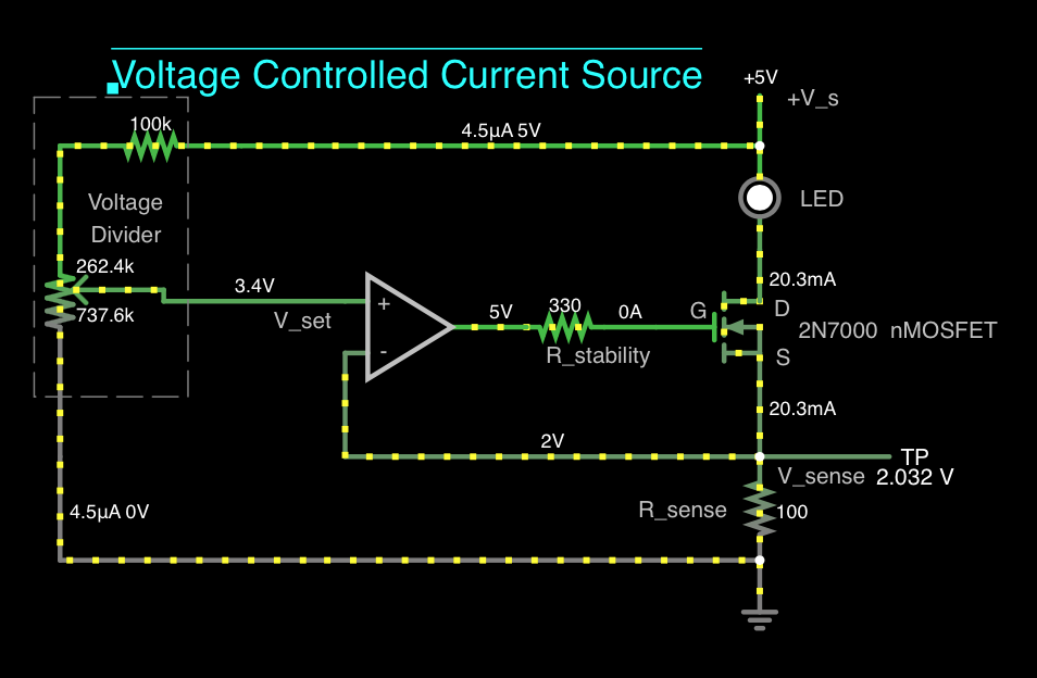
Simulation of voltage-controlled current source with a trimpot voltage divider supplying
Construct the above circuit shown using op amp A on your MCP6004 chip.
As usual, the op amp power connections and decoupling capacitors are not shown, but must exist.
Caution: You can easily destroy a MOSFET by zapping it with even small static shocks.
The resistance between the drain (
- Use the 2N7000 spec sheet has a diagram that clearly identifies its pins.
A MOSFET’s gate draws essentially no DC current, so the same current flows through the load LED and the sense resistor.
Use a clear white LED (20mA, 3.0-3.2V, 12000-14000 mcd) and choose a value for
Confirm that the LED’s brightness changes qualitatively as expected when you vary
- The LED may glow dimly even with
R-1) An op-amp with feedback tries to equalize the voltage at its two inputs. Explain why this implies
R-2) Is the current through the LED in your circuit linearly proportional to the set voltage over the full range of
- Note: The scope measurement functions cannot be trusted unless the volts/division are appropriate for the voltages you want to measure.
Do not disassemble this circuit; you’ll need it later.
Transimpedance Amplifier (Current Controlled Voltage Source)
- Transimpedance (“transfer impedance”) is the ratio of a circuit’s output voltage to its input current.
A photodiode produces a small current proportional to the optical power incident on it.
- Photodiodes have very large output impedance, so their output voltage will depend on the input impedance of whatever circuit they are driving unless that input impedance is huge.
- e.g. The photodiode output impedance is comparable to the input impedance of typical oscilloscopes and voltmeters, so the measured output voltage of an isolated photodiode will depend the scope used.
To measure the current from a TEFD4300 photodiode, convert it into a voltage using the transimpedance amplifier shown in the figure below.
A transimpedance amplifier using an op-amp, with a feedback resistor
- The photodiode only works if inserted the right way around.
- For diodes and capacitors with different length legs, the longer leg is positive.
- For diodes, the arrow points in the forward direction from + to -, and the bar on the physical diode corresponds to the line at the tip of arrow in diode circuit symbol.
- Use MCP6004 op amp B, C, or D. (A is in use for the previous circuit.)
The transimpedance amplifier takes advantage of the op amp’s low output impedance to decouple the photodiode signal voltage amplitude from the value of the input impedance of any subsequent circuit.
- The output voltage of this circuit is
Observe this output on your oscilloscope, and by covering and uncovering the photodiode, verify that the output voltage qualitatively depends on the light level.
- You may notice electrical mains (50/60Hz) noise.
R-3) Include a photo of your circuit, clearly showing the photodiode, capacitor, resistor, and op amp.
R-4) Include two screen captures of the scope showing the photodiode (Transimpedance Amplifier) output voltage (i.e.
Testing linearity
Place the photodiode and LED so they are point towards each other and are
Apply a 100 Hz, 1Vpp, 1ms wide Pulse bias voltage to
- A pulse signal is usually defined as a square wave that does not cross zero volts. The DSOX1204G Wave Generator is a a little idiosyncratic and requires some not obvious settings:
- In the Wavegen window, select:
- Select
Type: Pulse - Confirm (or set):
Frequency: 100.0Hz,High Level 1.00Vpp,Low Level 0Vpp,Offset: 0V,Width: 1ms
- Select
- Observe the pulses on your scope and confirm the bottom of the pulses is at 0 volts and the top of pulse is at 1V.
- In the Wavegen window, select:
- Adjust the trimpot to see a nice signal.
- If the photodiode output is much bigger than the WaveGen input, you may want to to reduce it by pointing the LED and photodiode away from each other. This will help with the bandwidth measurement later.
- Be sure to check that the signal goes away if a strip of black paper is inserted between the LED and the photodiode. If the signal does not go away, the signal is due to electronic cross-talk between your LED and Photodiode circuits, not light transmission between them.
- To get the cleanest signal, it is best to block or turn off any ambient light.
- Note: If the voltage divider did not have such high resistance, we’d have to think about whether the AC signal leaking into the op amp VDC power could be a problem.
Note: Falstad cannot simulate a photodiode, but if desired the LED flasher circuit can be simulated.
R-5) Include a photo of your circuit, clearly showing the LED and photodiode pointing directly at each other weith a small (mm) gap.
R-6) Include a screen capture / photo of the scope display showing the WaveGen input to the circuit and photodiode output.
R-7) Is the amplitude response of the combined system (WaveGen - VCCS - LED - photodiode - transimpedance amplifier) linear?
- i.e. Is the peak-to-peak voltage of the photodiode transimpedance amplifier output linearly proportional to the WaveGen set amplitude?
R-8) Is the bandwidth of the combined system (WaveGen - VCCS - LED - photodiode - transimpedance amplifier) consistent with the RC time constant expected from the feedback resistor and capacitor?
- Using your scope to make a Bode plot is the fastest way to do this.
- In the Frequency Analysis Settings you may want to reduce the Amplitude to 100mV
- Reminder: Bandwidths are defined by the frequency were the output is down by 3db from the maximum output, not by where the output is -3db relative to the input. For example, the maximum output of a circuit might be -6db relative to the input, so the “3db” points will be where the output is -9db.
Light Communication
Instead of driving the LED with with WaveGen, use the output from Arduino digital pin 8 instead. Load DigitalOutputPrimes.ino into your arduino and run. It sends sequences of pulses corresponding to the first 5 prime numbers, pauses, then repeats. It should work without modification.
- Sequences of prime numbers are favourite SETI search signals.
R-9) Include a photo of your complete working system: Arduino, LED, Photodiode, …
R-10) Make a screen shot or short video of your Scope showing the 5 prime number sequence being detected by the photodiode.
- If you are patient and set the Arduino sketch timings and scope timings suitably, you can catch the prime times in a single frame like this. Otherwise, make a short video.
- Don’t worry if the photo/video isn’t ideal, just as long as it is clear that the prime number sequence is being observed.
End of Lab
Looking Towards Final Project
This week’s exercise could again be the basis for a variety of final projects.
- e.g. You could investigate the maximum LED-photodiode distance over which messages could be transmitted, and investigate the effect of different R, C, LED, ….
Clean-up
- Properly dispose of any waste, e.g. wire or insulator cuttings
- But keep any small connector wires you may have made, they will be useful over the semester.
- If a component has been damaged, e.g. it smoked because of overheating, dispose it.
- Turn off all equipment.
See you in the next lab!
inspired by a previous write-up by Amar Vutha (2016-2018)↩︎